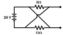
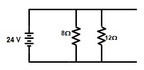
Ques 11. For the given circuit shown in the figure, the current supplied by the battery is
3A
2A
1.2A
5A✓
The given circuit can be reconstructed as shown in the figure
Now 8Ω and 12Ω are connected in parallel
(8 x 12)/(8 + 12) = 96/20 = 4.8Ω
Now current I = V/R = 24/4.8 = 5A
Ques 12. The angular velocity of a sinusoidal voltage is
ω = 1/T
ω = 2πf✓
ω = T/f
ω = 2π/f
Angular velocity is defined as the ratio of angular displacement to the time taken to undergo the displacement.
Angular velocity, ω = Angular displacement,θ/Time Taken T
θ = ωt
One complete rotation through 360° is an angular displacement of 2π radian
Angular velocity is rewritten as
ω = 2π/T = or ω = 2πf
Ques 13. At the instant of starting the slip of induction motor is
Unity✓
Zero
Leading
Lagging
Slip of an induction motor is given as
s = (Ns – Nr)/Ns
At the instant of starting the rotor is the standstill, therefore, Nr = 0
s = Ns/Ns =1
Ques 14. Inductance is the property of
Oppose the change in current✓
Oppose the change in voltage
Oppose in the change in frequency
Oppose in the change in resistance
An inductor is a device that temporarily stores energy in the form of a magnetic field. It is usually a coil of wire. One of the basic properties of electromagnetism is that when you have current flowing through the wire it creates a small magnetic field around it.
One current first start to flow through the inductor a magnetic field start to expand then after some time magnetic field becomes constant then we have some energy stored in the magnetic field.
Once a constant magnetic field is generated in the Inductor, it will not change any further. As magnetic flux = N x I (Turns x Current), Inductor will draw a constant current to maintain the magnetic field.
Once the current stop flowing the magnetic field start to collapse and the magnetic energy turned back into electric energy.
So when the current flowing through the inductor changes, the magnetic field also changes in the inductor and emf (electromotive force) is induced in the inductor as per Faraday’s law of electromagnetic induction.
According to Lenz’s law, the direction of electromotive force(emf) opposes the change of current that created it. V= -Lx dI/dt (rate of change of current)
So inductor opposes any change of current through them.
Ques 15. The rotor of an induction motor cannot run at synchronous speed because
Rotor torque would become zero✓
Stator flux would become zero
Losses would Increase
Induction motor would then become synchronous motor
An induction motor works on the principle of electromagnetic induction.
Now in an induction motor, we have a rotating magnetic field formed due to a three-phase supply.
When the motor is stationary then due to this rotating magnetic field an EMF is induced in the rotor (Generating Action).
Now rotor being shorted current starts flowing in it and due to motoring action torque is produced and the rotor starts rotating.
When the rotor tries to rotate with the synchronous speed but when it reaches that speed the relative motion between the magnetic field and conductor will become zero.
Emf generated is given by
E=B*L*V
where
V is relative velocity=Vs-Vr, L is the length of conductors, B is magnetic field density.
So now consider, the rotor of Induction Motor achieved synchronous speed then relative velocity would be zero as rotor speed equals to rotating magnetic field’s speed (Vs = Vr), thus emf generated will be zero.
No current flows through conductors so no force I.e. no torque. So because of the moment of inertia rotor will run even if emf is zero. And after some time, rotor speed decreases. again there would be relative velocity and again force-torque will generate making Induction Motor rotate at a speed less than synchronous speed
Ques 16. Which of the following instrument will give an accurate reading in both AC and DC instruments?
PMMC voltmeter
Dynamometer type wattmeter✓
Ampere Hour Meter
Induction Wattmeter
In Electrodynamometer for d.c, the deflection is proportional to the square of current For a.c the instantaneous torque is proportional to the square of the instantaneous current. The i2 is positive and as the current varies, the deflecting torque also varies.
Due to inertia, the moving system cannot follow rapid variations and thus final meter shows the average torque.
Thus the deflection is the function of the mean of the squared current. Therefore the scale is calibrated in terms of the square root of the average current squared ie. R.M.S. value of the A.C Quantity to be measured.
Note:-
PMMC measures the DC voltage and current only
Induction Wattmeter measure AC current or voltage only.
Ques 17. Leakage current allowed by the IE rules is:
1/500 part of the total current
1/1500 part of the total current
1/5000 part of the total current✓
1/3000 Part of the total current
Leakage currents
Leakage currents are involuntary currents that flow when a resource or electrical medical device is operating in a normal, faultless state. Therefore, leakage currents are not faulted currents.
The currents that flow from or between conductors that are insulated from the earth and from each other are called leakage currents and are normally small.
Fault currents only occur, as their name indicates, in the event of a fault (e.g. defective insulation). Leakage currents flow from live parts through the intact insulation to protective earth (PE conductor, potential equalization) or from a live part via the insulation to another live part.
Leakage currents are always present because there is no such insulation that insulates to 100% efficiency. Leakage currents are composed of ohmic and capacitive leakage currents.
As per Indian Electricity Rules, 1956, clause no. 49 (2) (b), the maximum leakage current allowable is one five-thousandth part (1/5000) part of the total current of maximum current supplied to the consumer’s installation. If the leakage current exceeds the above limit, the supply of electrical energy must be discontinued for safety reasons.
Even if there is no insulation failure, interruption of the leakage currents flowing through the ground conductor could pose a shock hazard to someone touching the ungrounded equipment and ground (or other grounded equipment) at the same time.
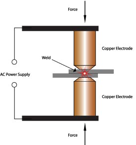
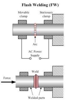
Ques 18. Commonly used method of welding to make lap welds in the thin sheet is:
Spot Welding✓
Carbon Arc welding
Flash Welding
Butt Welding
Spot welding is one of the oldest welding processes. Spot welding is one form of resistance welding, which is a method of welding two or more metal sheets together without using any filler material by applying pressure and heat to the area to be welded.
When similar materials are spot welded, then the highest resistance is between the interfaces of the two sheets, provided the correct welding conditions are used. When welding dissimilar metals, the maximum resistance may not exist at the interface; instead, it may be located within one of the metals if it has a higher specific resistance than the other metal.
A lap weld consists of two or more materials that are overlapped on top of one another. The edge of one material is melted and fused with the surface of another material. Among the various type of spot welding, lap welding and multiple lap welding is the most popular.
Butt weld:- Butt welding is a welding technique used to connect parts that are nearly parallel and don’t overlap.
Carbon arc welding (CAW) is a process that produces the coalescence of metals by heating them with an arc between a non-consumable carbon (graphite) electrode and the work-piece
Flash butt welding is one of the resistance welding processes employed to join metals. In the flash butt welding process, the ends of the piece are welded
Ques 19. The current transformer is used for
Measurement of Large alternating current✓
Measurement of Large DC current
Measurement of Frequency
Measurement of high voltage
Current transformers are generally used to measure currents of high magnitude.
The current transformer is used to step down the current to a lower value so that the current can be measured with a normal range ammeter.
The current transformer has a primary coil of one or more turns of thick wire connected in series.
The impedance of the primary is very low, and the currents very high. The primary current is dependent on the load on the line rather than the load on the secondary circuit.
Current drawn by the secondary has little effect on line current.
The secondary of the transformer contains many turns and has a much higher impedance. If the secondary is not loaded, this transformer acts to step up the voltage to a dangerous level, due to the high turns ratio. Because of this, a current transformer should always have a short-circuit placed across its secondary winding when connecting or removing any device from its output. By heavily loading the secondary, the high voltage is reduced to the safe level.
The nominal current rating of the secondary winding of the CT are 5A to 1 A.
To illustrate the operation of a current transformer, assume that the current ratio of the primary winding is 100 A. The secondary winding has a standard rating of 5A.
The primary winding consists of three turns of wire, and the secondary winding consists of 60 turns.
The ratio between the primary and the secondary currents is 100 A/5 A, or 20:1
In other words, the primary current is 20 times greater than the secondary current.
Note that the number of turns and the current in the primary and secondary windings are related by an inverse proportion. i.e I1 / I2 = N2 / N1.
By increasing the number of secondary windings, N2, the secondary current can be made much smaller than the current in the primary circuit being measured. In other words, as N2 increases, I2 goes down by a proportional amount.
Note:- As we know that the secondary of the transformer contains many turns hence the transformer acts to step up the voltage to a dangerous level, due to the high turns ratio. Because of this, a current transformer should always have a short-circuit placed across its secondary winding when connecting or removing any device from its output. By heavily loading the secondary, the high voltage is reduced to the safe level.
Ques 20. The active power in a delta-connected system of 440 V with a balanced load of the inductive reactance of 3Ω & resistance of 4Ω per phase is.
846.35 kW
28. 57 kW
1468 kW
92.92 kW✓
The voltage given in the above question is rated Line to Line Voltage because in the three-phase system the given voltage is rated line to line voltage and in the single-phase system, the voltage given is rated phase voltage.
Now the given quantities is Line voltage = 440 V
Inductive reactance = 3Ω and
Resistance = 4Ω
Then the given impedance of the circuit is
$Z = \sqrt {{3^2} + {4^2}} = 5$
Active power of Delta system is given as:
P3φ = √3 VLILcosφ
Now in delta connected system, the phase voltage is equal to the line voltage
VL = Vph = 440 V
And the Line current is √3 times the Phase current
IL = √3Iph
So phase current
Iph = Vph/Zph = 440/5 = 110V
Hence the line current will be equal to
IL = √3 x 88 = 152.42
Now Power factor cosφ is the ratio of Resistance to Impedance