Ques 32. When overexcited synchronous motor works as
Zero Power factor
Leading Power factor✓
Lagging Power Factor
Leading Power factor
A synchronous motor can operate at all the power factors.
At normal excitation, the synchronous motor works at the unity power factor.
If the field of a synchronous motor is under excited, then the power factor will be lagging and it acts as an inductor.
If the field of a synchronous motor is overexcited, then it acts as a synchronous capacitor and the corresponding power factor will be leading.
A synchronous motor running with no load will lead the current i.e. leading power factor like a capacitor. This synchronous motor running without load i.e. over-excited is a synchronous condenser.
The synchronous condenser is used in power lines to improve power factor, and power factor correction by connecting it along with transmission lines.
Ques 33. An electric bulb of rating 40W, 220V is used for 10 hours daily for 10 Days. Energy consumed is
5 kWh
3 kWh
6 kWh
4 kWh✓
Energy is given as
Energy = Power x Time = 40 x 10 x 10 = 4000W = 4kWh
Note:– If in the question the number of units consumed is asked then
1 unit = 1 kW h = 1000 W h = 4 unit
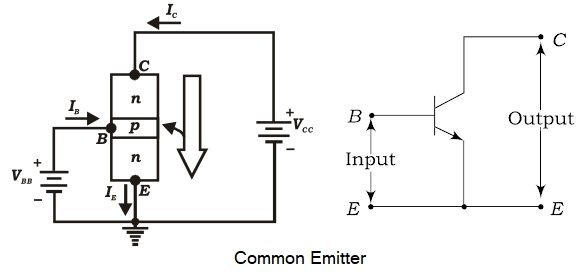
Ques 34. When used as an amplifier the transistor configuration will be given maximum gain
Common Emitter✓
Common Collector
Common Base
None of the above
Out of the three transistor connections, the common-emitter circuit is the most efficient. It is used in about 90 to 95 percent of all-transistor applications. The main reasons for this are :
The transistor circuit will have a moderately high input impedance
Low output impedance
Moderately high current gain
Moderately high voltage gain and very good and wide range of frequency response and hence find dominant applications in voltage, current and power amplifiers.
High current gain
In a common emitter connection, Ic is the output current and IB is the input current. The collector current here is expressed as:
Ic = βIB + ICEO Where β = Current Gain ICEO = Collector-Emitter current
As the value of β is very large, therefore, the output current IC is much more than the input current IB. This increases the current gain effectively. The current gain of CE arrangement ranges from 20 to 500.
High Voltage and Power Gain
As we have seen above, the CE arrangement has a high current gain. This in turn, increases the voltage and power gain of CE circuit. In comparison to CB and CC circuits, the common emitter connection has the highest voltage and power gain. For this reason, the CE transistor connection is often used for amplifying purposes.
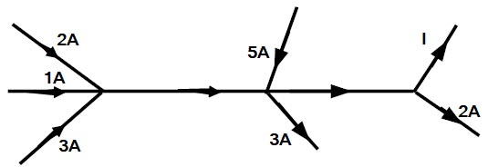
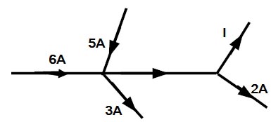
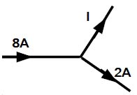
Ques 35. For the circuit shown in the figure Find I
1 A
0 A
6 A✓
3 A
Since in all the three branches the current is going in the same direction, therefore, all the current will add up.
2 + 1 + 3 = 6A
Now in the next branch 5A is coming in and 3 A is going out
Hence total current = 6 + 5 – 3 = 8A
In last Branch, 2A is going out hence the remaining current is
Insulation testing megger is a portable instrument used for testing the insulation resistance of a circuit, and for measuring the resistance of the order of megaohms in which the measured value of resistance is directly indicated on a scale.
Ques 37. The rate of consumption of 250 kWh at block rate tariff is quoted as
First 20 kWh at 60 paise/kWh
Next 25 kWh at 50 paise/kWh
Next 35 kWh at 40 paise/kWh
Exceeding 80kWh at 30 paise/unit
The average cost per unit consumption is
89.4 paise/kWh
53.8 paise/kWh
33.4 paise/kWh
35.8 paise/kWh✓
When a given block of energy is charged at a specified rate and the succeeding blocks of energy are charged at progressively reduced rates, it is called a block rate tariff.
The main consideration here is that as the number of units generated increases, the cost of generation per unit decreases. Therefore the consumer having the large demand in terms of the number of units have to pay less as compared to the consumers with lower demand. The energy consumption is divided into blocks and each block is charged at a fixed rate.
Now coming the question, as we know that 1 Unit is equal to 1 kWh therefore
The conductivity of water depends on the concentration of dissolved ions in the solution. Salt molecules are made of sodium ions and chloride ions.
(An ion is an atom that has an electrical charge because it has either gained or lost an electron.) When we put salt in water, the water molecules pull the sodium and chlorine ions apart so they are floating freely which is responsible for the conductance of electricity.
So, pure/distilled water is an extremely bad conductor, while impure water with ions in it is a good conductor
Ques 39. During charging the capacitor C = 100μF through a resistance of 1 KΩ applied with 100 V, the voltage of time constant is
63.7 V
36.7 V
63.2 V✓
100 V
An RC time constant tells us about the relation between time, resistance, and capacitance. The time taken by the capacitor is directly proportional to the amount of resistance and capacitance in the circuit.
The time constant reflects the time required for the capacitor to charge up to 63.2% of the applied voltage.
So 63.2% of 100 V = 63.2 Volt
Ques 40. The time multiplier of an inverse time relay is
TMS = T × TM
TMS = T/TM✓
TMS = TM/T
TMS = T × √2TM
An inverse time relay is one in which the operating time is approximately proportional to the magnitude of the actuating quantity. That is Operating time of the relay is inversely proportional to the fault current.
At values of current less than the Pickup value the relay never operates. At higher values, the operating time of the relay decreases steadily with the increase of current. The more pronounced the effect is the more inverse the characteristics is said to be.
Pick-up Value:- The minimum value of the operating quantity at which the relay is ready to operate.
The time multiplier setting of an inverse time relay is defined as:
TMS = T/TM
Where T = Actual time of operation Required TM = The time required for relay characteristics curve at TMS = 1.0 and using the PSM equivalent to the maximum current fault
PSM (Plug setting Multiplier)
It is the ratio of CT secondary fault current to the relay operating current.
Relay operating current = Current setting x CT secondary rated current
Thus, if the TMS is 0.1 and the time obtained from the curve, for a particular current is 4.0 seconds the actual operating time will be 4.0 × 0.1 = 0.4 seconds.
In other words, if the time from the curve is 4 seconds and the operating time required is 0.4 seconds the TMS should be 0.4/4 =1 sec
Ques 41. In capacitor start capacitor Run Motor, the starting and running capacitors respectively are
Mica capacitor, Oil capacitor
Electrolytic capacitor, Mica capacitor
Electrolytic capacitor, Oil capacitor✓
Oil capacitor, Electrolytic capacitor
The two-value capacitor is also known as capacitor start capacitor run the motor. The starting capacitor and running capacitor are connected in parallel.
Start capacitors briefly increase motor starting torque and allow a motor to be cycled on and off rapidly. A start capacitor stays in the circuit long enough to rapidly bring the motor up to a predetermined speed, which is usually about 75% of the full speed, and is then taken out of the circuit, often by a centrifugal switch that releases at that speed.
In the capacitor start the motor, the value of the capacitor is quite large, not possible with oil-filled or other types in reasonable size or economically feasible. Values can range normally anywhere from 40 mfd to 220 mfd, or even higher.
Electrolytic capacitors are cheaper and small enough for this application. However, losses in these capacitors are comparably quite high, and they get hot quickly. So they can remain in the circuit for a very short time, typically under 3 seconds, and need about 3 minutes gap before it can be reconnected.
An electrolytic capacitor is polar, which means it acts as the capacitor in one direction, while it behaves as the short circuit in the reverse direction.
Run capacitors are designed for continuous duty while the motor is powered, which is why electrolytic capacitors are avoided.
Oil-filled capacitors are nothing more than paper capacitors that are immersed in oil. The oil-impregnated paper has a high dielectric constant which lends itself well to the products of capacitors that have a high value.
Many capacitors will use oil with another dielectric material to prevent arcing between the plates. an arc should occur between the plates of an oil-filled capacitor, the oil will tend to reset the hole caused by the arc. These types of Capacitors are often called SELF-HEALING capacitors.
Ques 42. The approximate continuous rating of a motor for a load of 100 HP for 20 minutes at 3/4th load for next 10 minutes and a load for next 20 minutes is:
65 HP
97 HP
78 HP
72 HP✓
If a motor carries a load L1, for time t1 and load L2 for time t2 and so on, then
Average heating ∝ L21t1 + L22t2 +—————–L2ntn
In fact, heating is proportional to the square of the current but since load can be expressed in terms of the current drawn, the proportionality can be taken for bad instead of the current.
Ques 43. In a synchronous motor rotor, copper losses are met by
Supply Mains
DC Source✓
AC Input
Armature Input
The synchronous motor consist of the two parts:
Stator: Stator is the armature winding. It consists of three-phase star or delta-connected winding and excited by 3 phase A.C supply.
Rotor: Rotor is a field winding. The field winding is excited by the separate D.C supply through the slip ring.
The 3 phase Ac source feeds electrical power to the armature for the following component of the power (i)The net mechanical output from the shaft (ii) Copper losses in the armature winding (iii) Friction and the armature core losses
The power received by the DC source is used to be utilized only to meet copper losses of the field winding.