Ques 65. In the direct-online starter, NO-VOLT release is to
Safeguard the motor against the failure of the supply✓
Safeguard against earth fault
Safeguard against Overload
Safeguard against supply fluctuation
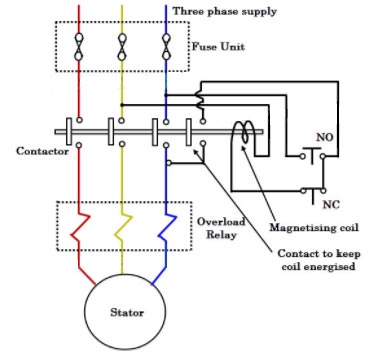
In case of small capacity motors having a rating of less than 5 hp. The starting current is not very high and such motors can withstand such starting current without any starter. Thus there is no need to reduce the applied voltage, to control the starting current. Such motors use a type of starter which is used to connect the stator directly to the supply lines without any reduction in voltage. Hence the &starter is known as the direct online starter.
Though this starter does not reduce the applied voltage, it is used because it protects the motor from various severe abnormal conditions like overloading, low voltage, single Chasing etc.
The NO contact is normally open and NC is normally closed. At the start, NO is pushed for fraction of a second due to which the coil gets energized and attracts the contractor. So stators directly get supply. The additional contact provided ensures that as long as the supply is ON, the coil gets supply and keeps the contactor in ON position. When NC is pressed, the coil circuit gets opened due to which coil gets de-energized and the motor gets switched OFF from the supply.
Under overload conditions, the current drawn by the motor increases due to which there is an excessive heat produced, which increases temperature beyond the limit. Thermal relays go open due to high temperature, protecting the motor from overload conditions.
Hence from the above it is clear that No Volt Coil ensures that whenever supply resumes after switching off or supply failure, the motor does not start on its own, but starts only after the user starts it and that too through current limiting resistors. When the supply voltage is below 85% of its rated voltage or it suddenly fails, the no volt-coil becomes demagnetized
Ques 66. What is the efficiency of the lamp of 230 V producing total flux of 3000 lumens when taking the current of 1 A
65
13✓
80
16
Lamp efficiency is given as
η =lumen/ Active power = lumen/ VIcosΦ
= 3000/230 x 1
= 13.04 lumens/W
Ques 67. In case of leading power factor, the terminal voltage of the alternator will
Fall on adding the full load
Rise on removing the full load✓
Fall on removing the full load
Rise on adding the full load
Under the load condition, the terminal voltage of the alternator is less than the induced e.m.f(Eph). So if the load is disconnected, Vph (per phase rated terminal voltage) will change from Vph to Eph, if flux and speed are maintained constant. This is because when the load is disconnected, Ia is zero hence there are no voltage drops and no armature flux to cause armature reaction. This change in the terminal voltage is significant in defining voltage regulation.
The voltage regulation of an alternator is defined as the change in its terminal voltage when the full load is removed, keeping field excitation and speed constant, divided by the rated terminal Voltage.
Soif Vph = Rated terminal voltage
Eph = No load induced e.m.f
Regulation = (Eph -Vph)/Vph
The value of the regulation not only depends on the load current but also on the power factor of the load.
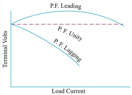
For lagging and unity p.f. conditions there is always drop in the terminal voltage hence regulation values are always positive.
While for leading capacitive load conditions, the terminal voltage increases as load current increases. Hence the regulation is negative in such cases. Hence the terminal voltage will fall on removing the full load.
The relationship between the load current and the terminal voltage is called the load characteristics of an alternator. Such load characteristics for various load power factor is shown in fig.
Ques 68. A three-phase circuit breaker rated at 1200A, 2000MVA, 100KV, 4sec. The rated symmetrical breaking
300 KA
11.55 KA✓
1.67 KA
20 KA
Breaking capacity = √3 × rated voltage in kV × Rated current in kA.
Rated MVA of circuit breaker = 2000 MVA
Rated MVA of CB = √ 3 × |V(line)|rated × Symmetrical breaking current
2000 x 103 = 1.732 × 100 × Symmetrical breaking current
Symmetrical breaking current = 11.54 KA
Ques 69. Dielectric heating is an industrial method employed for heating of
Insulating Material
Conducting Material
Liquids
Solid
Dielectric heating is an industrial method employed for heating of insulating materials.
Dielectric heating, also known as electronic heating, RF (radio frequency) heating, and high-frequency heating, is the process in which a high-frequency alternating electric field, radio wave or microwave electromagnetic radiation heats a dielectric material.
Dielectric heating (also called High-frequency capacitive heating) is employed for heating insulators like wood, plastics, and ceramics etc.
A non-conducting material generates heat when subjected to an alternation electric field. This process wherein heating takes place due to dielectric loss is known as dielectric heating.
The amount of heat produced depends on the value of the dielectric strength of the material. The non-conducting material acts as the job which is to be heated.
This method is extensively used in the plastic and wood industries. It is especially of immense utility where multiple woods are to be heated and glued. The heat supplied by this method is applied even] throughout the whole body. This method is also employed in the textile, rubber, chemical, and food industries.
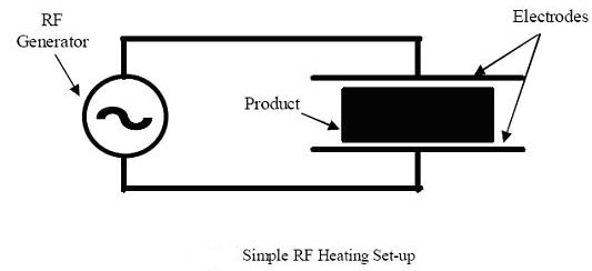
In this process, the job is placed in between two electrodes and the electrodes are fed with a very high-frequency supply. A capacitor is formed between the two electrodes and the job. The two electrodes act as the two plates of the capacitor and the job acts as a dielectric material between the two electrodes. The current flowing in the circuit is given by
Ic = E/Xc
Where Ic = current flowing through the capacitor in Amp
E = High-frequency supply voltage
Xc = Capacitive reactance in Ohm
During the charging and discharging of the capacitor, the molecular arrangement of the job changes because of the continuous stress created by the electric field. This change in molecular arrangement results in the generation of heat.
When a solid dielectric material (Insulating) is subjected to an alternating electric field, it is not supposed to carry any current. However, in practice, some leakage current passes through it and power loss is takes place. This loss is called as the dielectric loss and results in the heating of the dielectric material.
Ques 70. For an application that requires smooth and precise speed control over a wide range, the motor is preferred is
Squirrel cage Induction Motor
Synchronous Motor
DC motor✓
Wound Rotor Induction Motor
A DC motor is any of a class of rotary electrical machines that converts direct current electrical energy into mechanical energy. Controlling the speed of DC motors is a crucial matter since different machines and equipment have different aspects and output speed or torque requirements in which prospect.
Speed Control may require to be very precise and over wide ranges as well. So before implementing the proposed system an engineer needs to understand its operation and according to that how the speed of the drive wit] be controlled needs to be decided with proper care.
Generally, the rotational speed of a DC motor is proportional to the voltage applied to it, and the torque is proportional to the current. Speed control can be achieved by variable battery tapings, variable supply voltage, resistors, or electronic controls.
The direction of a wound field DC motor can be changed by reversing either the field or armature connections but not both. This is commonly done with a special set of contactors (direction contactors). The effective voltage can be varied by inserting a series resistor or by an electronically controlled switching device made of thyristors, transistors or, formerly, mercury arc rectifiers.
Speed control over a wide range both above and below the rated speed:
The attractive feature of the dc motor is that it offers a wide range of speed control both above and below the rated speeds. This can be achieved in dc shunt motors by methods such as armature control method and field control method.
This is one of the main applications in which dc motors are widely used in fine speed applications such as in rolling mills and in paper mills.
High starting torque:
DC series motors are termed as best suited drives for electrical traction applications used for driving heavy loads in starting conditions. DC series motors will have a starting torque as high as 500% compared to normal operating torque. Therefore dc series motors are used in the applications such as electric trains and cranes.
Accurate steep less speed with constant torque:
Constant torque drives are one such drives that will have motor shaft torque constant over a given speed range. In such drives, shaft power varies with speed.
Quick starting, stopping, reversing, and acceleration.
Free from harmonics, reactive power consumption, and many factors make dc motors more advantageous compared to ac induction motors.
Ques 71. The average of all the instantaneous values of a sinusoidal quantity over the cycle is:
0.707 times its maximum value
Maximum
Zero✓
Unity
Average Value:
The average of all the instantaneous values of an alternating voltage and currents over one complete cycle is called the Average Value.
If we consider symmetrical waves like sinusoidal current or voltage waveform, the positive half cycle will be exactly equal to the negative half cycle. Therefore the average value over a complete cycle will be zero. Hence the average value is calculated over the half cycle.
Ques 72. The power factor of the Parallel RLC circuit at resonance is
Zero
Unity✓
0.707 Leading
0.707 lagging
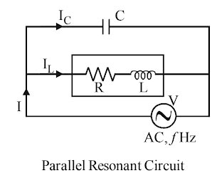
A parallel resonant circuit (also called an~resonanr or tank circuit) has a coil and a capacitor in parallel. It is said to resonate when the reactive (or wattless) component of line current I reduce to zero.
A practical parallel resonance circuit is represented by an inductance and a resistance in one branch and a capacitance in other branches.
At resonance in a practical parallel resonance circuit, the impedance is maximum. Hence, it is called a rejector circuit and exhibits the property of voltage magnification.
Z = L/CR
The line current in the parallel resonance circuit is minimum.
I = V/L/CR
Different possible definitions of the resonant frequency for a parallel resonant circuit:
The frequency at which ωL = 1ωC i.e., the resonant frequency of the equivalent series RLC circuit. This is satisfactory if the resistances are small.
The frequency at which the parallel impedance is a maximum.
The frequency at which the current is in phase with the voltage, unity power factor.
At the time of resonance, the parallel resonance RLC circuit becomes purely resistive.
Ques 73. According to double-revolving field theory, the rotor of single phase induction motor may be visualized as
Two rotors running in opposite direction with the different stator winding
Two rotors running in the same direction with the common stator winding
Two rotors running in the same direction with the different stator winding
Two rotors running in the opposite direction with the common stator winding✓
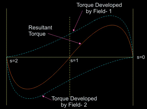
The working principle of an ac machine is primarily “one field following another field”. In the case of a multiphase induction motor, there will be a virtual rotating magnetic field. But considering the case of a single-phase induction motor, it’s only a pulsating field that is produced and not a rotating one. This can also be explained on the basis of ‘DOUBLE REVOLVING FIELD THEORY‘, which is based on the Ferraris Principle
As per Ferrari’s principle, the alternating magnetic field produced by the stator can be split into two rotating magnetic fields of half the magnitude and rotating at synchronous speed in opposite directions. When the alternating supply is fed to the stator winding, an alternating flux is developed This flux rotates and cuts the rotor conductors. Due to this, an EMF is induced. As the rotor circuit is closed the current flows through the rotor conductor. This rotor current will cause rotor flux. and at any instant, its magnitude is given by,
φs = φm COS ωt
where φm is the maximum flux developed in the motor. According to this theory, the alternating flux φs can be resolved into two components of and φf & φb such that the magnitude of by φf & φb is equal to half the magnitude of φs . Let us assume that φf rotates in a clockwise direction and φb rotates in the anti-clockwise direction.
An emf is induced in the rotor circuit due to each rotating field. If the polarity of the induced emf in the rotor due to φf is taken as positive then emf induced in the rotor due to φb is negative (i.e. in phase opposition). As, at standstill, the slip in either direction is the same (i.e. s = 1), the rotor impedance will also be the same. Thus, the rotor currents are equal, but opposite in phase that is the starting torque developed by each revolving field is the same, with one acting in forwarding direction and the other acting in the backward direction. Thus, the net torque developed by the motor is zero.
Based on double-revolving field theory, a single-phase induction motor can be visualized as having two rotors revolving in opposite directions with a common stator winding. At standstill, the two rotors develop equal torques in opposite directions and hence the net torque developed is zero.
Ques 74. 1 Volt is equal to
1 watt/Ohm
1 joule/coulomb✓
1 Joule/1 Watt
1 Watt /1 Coulomb
1 volt define in various ways:
One volt is defined as energy consumption of one joule per electric charge of one coulomb. 1V = 1J/C.
One volt is equal to the current of 1 amp times the resistance of 1 ohm.
1V = 1A × 1Ω
Collection of one Columb charge on unit farad capacitor is one volt.
1 V = q × C =1c × 1F
Ques 75. A fractional horsepower motor has power less than
100 Watt
1 Mega Watt
1 Watt
1 kiloWatt✓
A fractional horsepower motor (FHP) is an electric motor with a rated output power of 746 Watts or less.
The term ‘fractional‘ indicates that the motor often has a power rating smaller than one horsepower.
Hence the power infraction horsepower Motor is always less than 746 watt