
Ques 21. The power in delta connected system is _____ times the power in the star system.
- 1/√3
- 2
- 1/3
- 3✓
Let us suppose Vs be the supply voltage per phase. Now assume any type of load; for simplicity, let’s assume it a resistive load which is R per phase For star system Phase voltage VPh = VL/√3 And Phase current Iph = IL = Vph/Rph For 3 phases Power is given as P3Φ = 3 × I2ph x Rph = V2L/R ————1 Now for Delta connection Phase voltage = Line voltage VPh = VL And Phase current Iph = IL/√3 = Vph/Rph Power P3Φ = 3 × I2ph × Rph = 3V2L/R ————2 From the above two-equation, it is clear that the power in delta connected system is 3 times the power in the star system.
or
P3Φ = 3 × (VL/√3 Rph)2 Rph
or
P3Φ = 3 x (VL/Rph)2 Rph
Ques 22. In FHP induction motor, splitting the phase is done using
- Resistance/Inductance
- Only capacitor
- Only resistance
- Resistance/Capacitor✓
The start winding and run winding are already inductors, so adding inductance in series with the start winding does not produce much phase difference between the start and run windings. The capacitor is used in a single-phase Induction motor for creating a phase shift. The addition of a capacitor creates the phase shift of 90 degrees in time between these two windings which makes it self-starting. The addition of the inductor will be of no use as this won’t make the motor as self-starting ( even if it starts it will rotate at very very less speed) and inherently will lead to an increase in losses only. Moreover, a high valued inductor can split the phase of the existing windings but it won’t be a good practice to add an inductor of high value to split the phase (incurring low pf and losses).
Ques 23. The value of free density copper is
- 8 x 1028/m3
- 1.69 x 10¹⁹/m3
- 8.5 x 1028/m3✓
- 16 x 1028/m3
Cooper is monovalent, which means there is one free electron per atom. the density of the copper atom is n = 8.5 x 1028/m3 We can solve it by the following formula Where NA is Avogadro constant D is the density of copper = 8900 kg/m3 The atomic weight of copper is = 63.5 The conductivity of the copper is σ = 5.9 x 10⁷Ω/m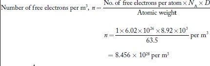
Ques 24. Buchholz relay is used for the protection
- Alternator
- AC motor
- DC motor
- Transformer✓
The Buchholz relay is a gas-operated relay used for the protection of oil-immersed transformers against all types of internal faults. The slow-developing faults called incipient faults in the transformer tank below oil level operate Buchholz relay which gives an alarm. If the faults are severe it disconnects the transformer from the supply. It uses the principle that due to the faults, oil in the tank decomposes, generating the gases. The 70% component of such gases is hydrogen which is light and hence rises upwards towards the conservator through the pipe. The Buchholz relay is connected to the pipe, as shown in Fig. Due to the gas collected in the upper portion of the Buchholz relay, the relay operates and gives an alarm. There are many types of internal faults such as insulation fault, core heating, bad switch contacts, faulty joints, etc. which can occur. When the fault occurs the decomposition of oil in the main tank starts due to which the gases are generated. As mentioned earlier, the major component of such gases is hydrogen. The hydrogen tries to rise up towards the conservator but in its path, it gets accumulated in the upper part of the Buchholz relay. When gas gets accumulated in the upper part of the housing, the oil level inside the housing falls. Due to this the hollow float tilts and closes the contacts of the mercury switch attached to it. This completes the alarm circuit to sound an alarm. Due to this operator knows that there is some incipient fault in the transformer. The transformer is disconnected and the gas sample is tested. The alarm circuit does not immediately disconnect the transformer but gives the only indication to the operator. This is because sometimes bubbles in the oil circulating system may operate the alarm circuit though there is no fault. However, if a serious fault such as an internal short circuit between phases, earth fault inside the tank, etc. occurs then a considerable amount of gas gets generated. Thus due to the fast reduce the level of oil, the pressure in the tank increases. This energizes the trip circuit which opens the circuit breaker. Thus transformer is totally disconnected from the supply. The connecting pipe between the tank and the conservator should be as straight as possible and should slope upwards the conservator at a small angle from the horizontal This angle should be between 10 to 11° For the economic considerations, Buchholz relays are not provided for the transformers having a rating below 500 kVA.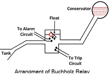
Ques 25. The equivalent inductance (L1) of two inductors LA and LB in series having the mutual inductance of M with the cumulative connection is
- L1 = LA + LB + 2M✓
- L1 = LA + LB – 2M
- L1 = LA – LB + 2M
- L1 = LA – LB – 2M
When inductors are connected together in series so that the magnetic field of one links with the other, the effect of mutual inductance either increases or decreases the total inductance depending upon the amount of magnetic coupling. The effect of this mutual inductance depends upon the distance apart of the coils and their orientation to each other. Mutually connected inductors in series can be classed as either “Aiding” or “Opposing” the total inductance. Cumulative connection Two coils are said to be cumulatively coupled if their flux is always in the same direction at any instant. or If the magnetic flux produced by the current flows through the coils in the same direction then the coils are said to be Cumulatively Coupled. Let the self-inductance of each individual coil, L1, and L2 respectively. The mutual inductance between both the coil be M If current flow through the circuit is changing at the rate of di/dt then total emf induced will be due to self-induced e.m.f.s and due to mutually induced em.f. Due to flux linking with coil 1 itself, there is self-induced e.m.f., e1 = −L1di/dt Due to flux produced by coil 2 linking with coil 1, there is mutually induced e.m.f. e1 = −Mdi/dt Due to flux produced by coil 1 linking with coil 2, there is mutually induced e.m.f., e2 = −Mdi/dt Due to flux produced by coil 2 linking with itself, there is self-induced e.m.f. e2 = −L2di/dt Then the total induced E.M.F is the addition of the these E.M.F as all are in the same direction e = e1 + e21 + e12 + e2 = −L1di/dt + −Mdi/dt + −Mdi/dt + −L2di/dt = −[L1 + L2 +2M]di/dt Since both coils are connected in series can be considered as a single coil with equivalent inductance Leq. The emf induced in the equivalent single coil with the same rate of change of current is given by, Total Induced EMF induced = −Leqdi/dt −Leqdi/dt = −[L1 + L2 +2M]di/dt Leqdi/dt = −[L1 + L2 +2M]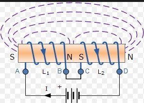
Ques 26. The energy meter is designed to make 100 revolutions for one unit of energy. The number of revolutions when connected to the load of 40A, at 230 V and 0.95 Power factor lagging for an hour is.
- 530
- 874✓
- 362
- 657
Energy Meter constant K = 100 revolution/kWh Load current I = 40 A Supply voltage V = 230 V Power factor Cosφ = 0.95 Since power is the rate of energy per time Therefore Energy = Power x Time Et = VICosφt = 230 x 40 x 0.95 x 1 = 8740 Watt = 8.74 kW Meter constant K = Number of revolution/Energy supplied in Killo-watt hour = 100 = Number of revolution/8.74 Number of revolution = 874
Ques 27. The transformer core are laminations are insulated from each other by
- Cotton
- Paper
- Mica Strip
- The thin coating of Varnish✓
The purpose of providing the coating of varnish in windings are
Ques 28. Active power in a 3 phase system may be calculated as
- P = √3 Vph Iph cosφ
- P = √3 VL IL cosφ✓
- P = VL IL cosφ
- P = √3 VL IL
The active power in the star and delta connection is the same Now consider a delta connection system In Δ connection, line voltage is equal to phase voltage, as each winding is connected between any two lines. Therefore, VL = Vph Let the RMS value of the current of the three phases be IB, IR, IY. Let the direction of the currents be as shown in the figure. Since the loads are balanced, all the three currents will be equal in magnitude but will differ in phase by 120°.It is seen from the figure that lR when positive will flow away from the line conductor R. Similarly, IY flows away from the line conductor Y. and IB flows away from the line conductor B. Now If we consider the line conductor R, then the current IB flows towards it while current IY flows away from it. Hence in Δ connection, current in any line is equal to the phasor difference of the current in two phases connected to the line. Thus, Current in Line R = IR − IB As the current inline R is the phasor difference between IR and IB, it is obtained by subtracting IB from IR. To do this, phasor IB is reversed as shown in fig. such that (IR – IB) becomes [IR + (-IB)]. From the phasor diagram, it is observed that the two phasors IR and -IB are equal in magnitude and are displaced at 60°. So, the current in line R. IR − IB = 2Iph cos(60°/2) = 2Iph cos30° = √3 Iph Similarly current in Line Y = IY − IR = √3 Iph current in Line B = IB − IY = √3 Iph Thus, in a balanced three-phase delta connection, line current = √3 x phase current. It is also noted the line current IR − IBlags behind the phase current IR by 30°.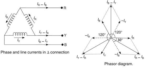
Current in Line Y = IY − IR
Current in Line B = IB − IY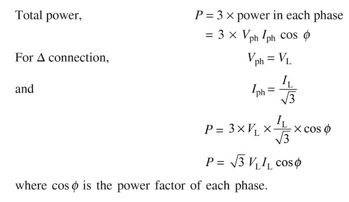
Ques 29. Select the wrong statement coils of an electric kettle and electric irons are made of alloys rather than pure metal because.
- Alloys do not oxidize easily
- Resistive changes are less rapid in an alloy than in pure metal
- The resistivity of alloys is higher than that of the metal
- Thermal expansion of alloys is lesser than that of the pure metal✓
The heating elements (or heating coils) of electrical heating appliances such as electric iron and toaster, etc., are made of an alloy rather than a pure metal because
Ques 30. Find the current transformer measurement, if a 100:5 CT is used in conjunction with (0 – 5A) ammeter reads 3A
- 60 A✓
- 35 A
- 15 A
- 70 A
The ratio between the primary and the secondary currents is 100 A/5 A, or 20:1. In other words, the primary current is 20 times greater than the secondary current. Note that the number of turns and the current in the primary and secondary windings are related by an inverse proportion. i.e I1 / I2 = N2 / N1. A current transformer (CT) has the large load currents connected to the primary winding of the transformer and the ammeter connected to the second winding. If the ammeter reads 3A that means the current in the secondary winding is 3A. If the turn ratio is kept constant then-new primary current is Now I1 / I2 = I’1 / I’2 100/5 = I’1 / 3 I’1 = 60 A
Ques 31. The scientist who first discovers the relationship between the electricity and magnetism is
- Hans Christian Oersted✓
- Michael Faraday
- Thomas Alva Edison
- Ohm
Hans Christian Oersted was a Danish physicist and chemist who discovered that electric currents create magnetic fields, which was the first connection found between electricity and magnetism. He was born on August 14, 1777 – and died on Mach 09, 1851. Oersted is still known today for Oersted’s Law, electric current, electromagnetism, piperine discovery, and finally formulation of metallic aluminum. The centimeter-gram-second system (CGS) unit of magnetic induction (oersted) is named for his contributions to the field of electromagnetism. In the year 1820 Oersted discovered that a magnetic needle aligns itself perpendicularly to a current-carrying wire, definite experimental evidence of the relationship between electricity and magnetism. Other important works of Oersted include piperine alkaloid, in 1825 he produced aluminum. He was the first to isolate the aluminum element via a reduction of aluminum chloride with potassium amalgam. Note:- Michael Faraday FRS (22 September 1791 – 25 August 1867) was an English scientist who contributed to the study of electromagnetism and electrochemistry. His main discoveries include the principles underlying electromagnetic induction, diamagnetism, and electrolysis. Thomas Alva Edison (February 11, 1847 – October 18, 1931) was an American inventor and businessman, who has been described as America’s greatest inventor. He developed many devices that greatly influenced life around the world, including the phonograph, the motion picture camera, and the long-lasting, practical electric light bulb. Georg Simon Ohm Discovered Ohms law

