Ques 81. Which switch is used for the automatic control of the motor?
Hand OFF auto switch
Hand ON auto Switch
Rheostatic switch
Any of the above
Answer.1. Hand OFF auto switch
Explanation:-
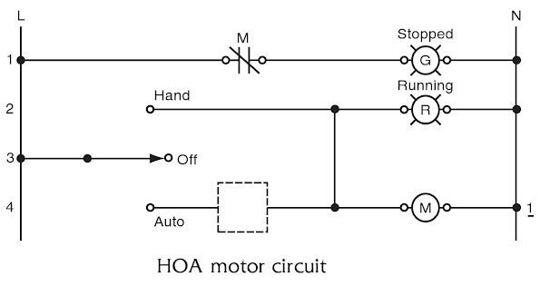
Starting or stopping some motors automatically is very useful. The ability to control the motor manually is usually retained. That is, the motor control is provided with a selector switch to select either manual or automatic control. A very common selector switch used for this purpose is called a hand-off-auto switch (HOA). These switches have three possible positions—hand, off, or auto. The symbol for an HOA switch is shown in Figure
Because the HOA selector switch is a maintained switch, it operates in the same manner as the local-remote switch example. When it is used in a control circuit, it looks like Figure 3-18.
As shown, the electricity must first flow through the HOA switch before it can energize the coil of the motor contactor. To get through the switch, the switch must be in the hand or auto position. If it is in the hand position, the current can flow straight to the motor contactor’s coil, causing the motor to run any time the HOA switch is in the hand position. If the HOA switch is in the off position, there is no path for the electricity to get to the contactor’s coil, and, therefore, the motor cannot run. If the HOA switch is in the auto position, then there must be some other switch used in the dotted box to allow the current to flow through to the contactor’s coil.
Ques 82. _________ are nonmanual control switches activated by an unsafe condition.
Switches
Gear
Interlock
None of the above
Answer.3.Interlock
Explanation:-
Interlock is nonmanual control switches that are activated during the motor abnormal condition.
Ques 83. Typically, interlocks stop motors _________ but do not start motors ________
Manually, automatically
Automatically, manually
Automatically, Automatically
Manually, Manually
Answer. 3.Automatically, Automatically
Explanation:-
Typically, interlocks stop motors automatically but do not start motors automatically. A few examples of interlocks are
Motor overloads
The low level on the suction side of a water pump
High discharge pressure on a positive displacement pump
High torque on a conveyor belt
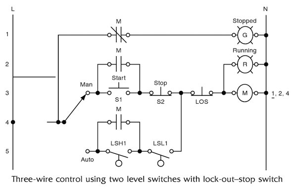
Interlocks are intended to protect human life or equipment, so they are designed to function regardless of whether a manual or automatic control is in use. Therefore, they are wired in a motor control circuit on the line side of other devices, for example, if there is concern that a sump pump will burn out if it is operated when there is no water in the sump. Because this could damage the pump even if it is being operated manually, it would be best to create an interlock for it. To create this interlock, an additional low-level switch is installed in the sump that operates at a level below the low-level switch used to turn the motor off in the automatic mode as described for the three-wire control version. This extra low-level switch would be labeled LSLL, the two Ls on the end to mean low-low (lower than low). Similarly, a high-value interlock might be labeled HH for high-high (higher than high). This LSLL would then be wired into the circuit between the line side of the ladder and the man-auto switch, as shown in Figure.
The LSLL contact must be closed in order to run the motor in either the manual mode or the automatic mode. Also, the green stopped light will not be illuminated if the LSLL is not closed. Interlocks are often wired in a way that extinguishes all status indicating lights so that if all indicating lights are out, it indicates that an interlock has been tripped. When the green light is wired this way, it is often engraved ready instead of stopped. The green light is illuminated only if the motor is ready to run. Of course, if the green light was burned out, it would falsely indicate that an interlock was tripped. However, most indicating lights are the push-to-test type, which means that the light’s lens is actually a push button that can be pressed to illuminate the light regardless of the current status of the motor. Therefore, simply pushing the light’s lens will determine whether the problem is a burned-out bulb or if an interlock has been tripped.
Ques 84. The DC shunt motor is running with a certain load. The effect of adding an external resistance in field circuit is to:
Increase the Motor Speed
Stop the Motor speed
Reduce the motor Speed
Reduce the armature speed
Increase the Motor Speed
Explanation:-
Flux Control Method:-
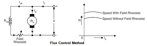
Flux control method is based on the fact that by varying the flux A, the motor speed (N ∝ 1/φ) can be changed and hence the name flux control method. In this method, a variable resistance (known as silent field rheostat) is placed in series with shunt field winding as shown in Fig
The shunt field rheostat reduces the shunt field current Ish and hence the flux φ. Therefore, we can only raise the speed of the motor above the normal speed. Generally, this method permits to increase the speed in the ratio 3: 1. Wider speed ranges tend to produce.
Advantages
Easy and convenient method.
It is an inexpensive method since very little power is wasted in the shunt field rheostat due to the relatively small value of Ish.
The speed control exercised by this method is independent of the load on the machine.
Disadvantages
Only speeds higher than the normal speed can be obtained since the total field circuit resistance cannot be reduced below Rsh i.e the shunt field winding resistance.
(ii) There is a limit to the maximum speed obtainable by this method. It is because if the flux is too much weakened, commutation becomes poorer.
Ques 85. The three-point starter can be used for
Both shunt and compound Motors
Shunt Motor Only
Series Motor Only
Compound Motor Only
Answer.1.Both shunt and compound Motor
Explanation:-
3 point starters in DC Shunt and Compound machines serve for following purposes.
It limits the high starting current into the armature by having the resistance high at the time of starting and reducing it during the running conditions.
It also protects the motor from overload and under voltage conditions.
Ques 86. DC motor is recommended for the Locomotive drive is:
DC series Motor
DC long shunt compound Motor
DC Shunt Motor
DC short shunt compound Motor
Answer.1.DC series Motor
Explanation:-
In trains or bus there are many compartments full of passengers & luggage, so during the starting, it requires high starting torque. Dc series motor is used for the locomotive because it has very high starting torque and variable speed.
DC series motors will have a starting torque as high as 500% compared to the normal operating torque
Ques 87. In the case of a 3 phase induction motor, plugging is done by:
Starting the motor on load which is more than the rated load
Pulling the motor directly on line without a starter
Interchanging connections of any two phases of the stator for quick stopping
Locking of the rotor due to harmonics
Answer. 3.Interchanging connections of any two phases of the stator for quick stopping
Explanation:-
It is known that the rotor of a polyphase induction motor develops torque in the same direction as the rotating magnetic field set up by the stator winding. Also if any two stator leads are reversed, the rotating magnetic field is also reversed. lf therefore, the pair of stator leads ore reversed while a motor is rotating, torque is suddenly-produce opposite to the original direction of rotation. This reverse torque causes rotation in the opposite direction as soon as the motor stops, therefore provision must be made to disconnect stator completely from the supply lines when the motor stops.
Hence Plugging in induction motor braking is applied by just reversing the supply phase sequence by interchanging connections of any two phases of the stator, we can attain plugging braking of an induction motor. Due to the reversal of phase sequence, the direction of rotating magnetic field gets reversed. This produces a torque in the reverse direction and the motor tries to rotate in opposite direction.
This opposite flux acts as the brake and it slows down the motor. During plugging the slip is (2 – s), if the original slip of the running motor is s.
Note : The method can be applied to both squirrel cage as well as wound rotor induction motors.
Ques 88. Deep bar rotor construction is used in three-phase induction motors to mainly:
Control Speed
Control Power Factor
Increase the Starting Torque
None of these
Answer.3. Increase the starting Torque
Explanation:-
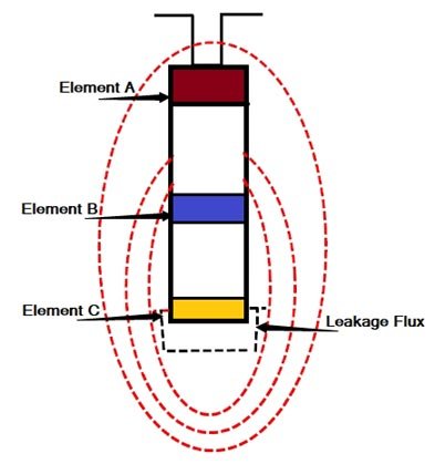
There is no constructional difference between stator of deep bar motor and that of an ordinary induction motor. The rotor consist of deep bars, short-circuited by two end rings one on each side. A bar may be assumed to be made up of the number of narrow layers connected in parallel. It is seen that the topmost layer element is linked with minimum leakage flux and therefore its leakage inductance is minimum. On the other hand, the bottom layer links maximum flux, therefore its leakage inductance is maximum.
At starting the rotor frequency is equal to the supply frequency. The bottom layer element offers more impedance to the current flow then upper layer hence the maximum current flows through the top layer and minimum through the bottom layer. This unequal current distribution causes the effective rotor resistance to increase. With a high rotor resistance at starting condition, the starting torque is relatively high & starting current is low as desired.
Now under normal operating conditions, the slip and the rotor frequency are very small. The reactance of all the layers is small compared to their resistances. The impedances of all the layers are nearly equal, so current flows through all the parts of the bar equally. The resulting large cross-section area makes rotor resistance small, resulting in good efficiency at low slips.
Ques 89. In a 3-phase voltage source inverter used for speed control of induction motor, antiparallel diodes are used across each switching device. The main purpose of diodes is to:
Protect the switching devices against overvoltage
Provide the path for freewheeling current
Allow the motor to return energy during regeneration
Help in switching off the devices
Answer. 3.Allow the motor to return energy during regeneration
Explanation:-
In regenerative braking, the motor, instead of being disconnected from the supply, remains connected to the supply and returns the braking energy to the supply line.
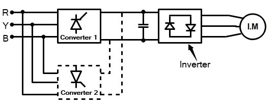
VSI fed IM drive has a voltage source inverter at the machine end and a six-pulse converter at the source end. When the induction machine is motoring, the source end converter operates as a rectifier, and the machine end converter operates as an inverter.
With a single 6 pulse converter at the input side, regeneration is not possible since the electrolytic capacitor does not allow reversal of the voltage Polarity and the SCRs do not allow the reversal of currents.
Regeneration is possible by having an antiparallel 6 pulse converter at the input side. When regeneration takes place, firing pulses to converter 1 are stopped and firing pulses are given to the machine end converter such that it operates as an inverter. The motor operates as an induction generator since it converts mechanical power into electrical power. The diode rectifier part of VSI converts AC to DC. Converter II converts DC power into AC power and is fed to the AC mains. The disadvantage being that an additional six-pulse converter is required for regeneration.
Ques 90. A 3-phase delta connected squirrel cage induction motor when started with a DOL starter has a starting torque of 600 NM. Its starting torque when star delta starter is used:
600 NM.
200 NM
300 NM
1200 NM
Answer.2.200 NM
Explanation:-
Starting torque of star delta starter is equal to 1/3 of its delta value