Ques 11. A silicon PN junction in forward conduction has a voltage drop closer to
1.7 V
2.1 V
0.1 V
0.7 V✓
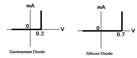
A diode requires that the potential barrier voltage of its PN junction must be overcome before it can be forward biased on. This barrier voltage and the actual forward bias voltage drop of a diode depend upon the material and construction of the diode.
The barrier potential and the actual voltage drop in a live circuit of a germanium diode is about 0.2V and a silicon diode is about 0. 7V. The germanium diode must have at least 0 2 V applied to it by the circuit to turn it on and conduct, otherwise, it draws 0 A (Acting like an open circuit). The silicon must have at least 0.7 V applied to it for the diode to turn on and conduct.
Once the diode turns on, it continues to drop the barrier voltage across the diode. Thus, once a silicon diode turns on, it maintains a drop of about 0.7 V. The voltage of the on diode remains fairly constant, with relatively large swings in diode current. For example, an on silicon diode current may double from 10 mA to 20 mA but still maintain a voltage drop of about 0.7 V. If the voltage across the diode drops much below 0.7 V, Diode turns off and becomes ideal open circuit.
Ques 12. Resonance in RLC series Circuit Occurs at a frequency
$f = \dfrac{1}{{2\pi \sqrt {LC} }}$✓
$f = \dfrac{1}{{2\sqrt {LC} }}$
$f = \dfrac{1}{{\pi \sqrt {LC} }}$
$f = \dfrac{1}{{\sqrt {LC} }}$
The resonance of a series RLC circuit occurs when the inductive and capacitive reactances are equal in magnitude but cancel each other because they are 180 degrees apart in phase. Since in resonance condition, the Inductive reactance XL is equal to capacitive reactance XC i.e XL = XC
Ques 13. A fused material should possess the following properties
Low melting point and low specific resistance✓
High melting point and High specific resistance
Low melting point and high specific resistance
High melting point and Low specific resistance
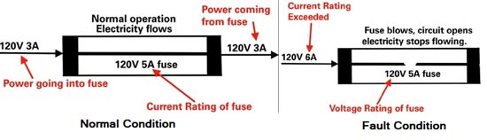
Fuse is the current interrupting device which breaks or open the circuit (in which it is inserted) by fusing the elements when the current in the circuit exceeds a certain value.
Characteristics of a fuse are:-
It should have the low melting point.
It should have low ohmic losses.
It should have high conductivity. ( or low resistivity)
It should be economical.
It should be free from detraction.
Ques 14. The magnetic field intensity in a material whose relative permeability is 1 when the flux density is 0.005 T is:
250 AT/m
452 AT/m
1775 AT/m
3980 AT/m✓
Magnetic field Intensity H is is given as
H = B/μrμo
Where
B = flux density μo = Permeability of free space or magnetic space constant. Its value is 4π × 10-7 H/m, μr = Relative Permeability
H = 0.005/1 × 4π × 10-7 = 3980 AT/m
Ques 15. In the maximum power transfer theorem, the power delivered to load resistance is given by
${P_{\max }} = \dfrac{{{V^2}}}{{4{R_L}}}$✓
${P_{\max }} = \frac{V}{{4{R_L}}}$
${P_{\max }} = \frac{{{V^2}}}{{4{R_L}^2}}$
${P_{\max }} = \frac{V}{{4{R_L}^2}}$
Maximum Power TransferTheorem
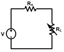
Maximum Power Transfer Theorem can be stated as – A resistive load is connected to a DC network, receives maximum power when the load resistance is equal to the internal resistance known as (Thevenin’s equivalent resistance).The maximum power transfer theorem is applied to both the DC and AC circuit. The only difference is that in AC circuit the resistance is substituted by the impedance.
Let V be the voltage source, Rs be the internal resistance of the source and RL be the load resistance or the Thevenin resistance.
Ques 16. The method of speed control of DC Shunt motor is used for applications where a very wide range sensitive speed control is required is
Ward-Leonard system✓
Multiple Voltage Control
Tapped field control
Rheostatic Control
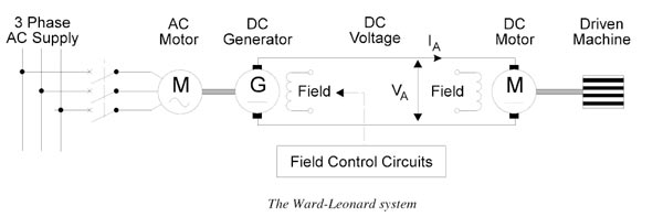
Ward-Leonard system.
The Ward-Leonard system comprises a fixed speed 3-phase AC induction motor driving; separately excited DC generator that, in turn, feeds a variable voltage to a shunt wound DC motor. So this is essentially a DC variable speed drive.
The basic principle of the DC variable speed drive is that the speed of a separately excited DC motor is directly proportional to the voltage applied to the armature of the DC motor. The main changes over the years have been concerned with the different methods of generating the variable DC voltage from the 3-phase AC supply.
In the case of the Ward-Leonard system, the output voltage of the DC generator, which is adjusted by controlling the field voltage, is used to control the speed of the DC motor.This type of variable speed drive had good speed and torque characteristics and could achieve a speed range of 25:1. It is no longer commonly used because of the high cost of the 3 separate rotating machines. In addition, the system requires considerable maintenance to keep the brushes and commutators of the two DC machines in good condition.
Advantages of Ward-Leonard system.
Wide range of sensitivity can be obtained by using this method.
The absence of an external resistance improves the efficiency at all speeds.
No special starting gear is required
As the generator induced voltage is gradually raised from zero, the motor starts up smoothly
Speed reversal is smoothly carried out.
Disadvantages of Ward-Leonard system.
The Initial cost of the system is high as there is a motor generator set installed, of the same rating as that of the main DC motor.
Larger size and weight.
Requires large floor area
Costly foundation
Maintenance of the system is frequent.
The overall efficiency of the system is not sufficient, especially it is lightly loaded.
Application of Ward-Leonard System
Colliery Winders
Cranes
Electric Excavators
Mine hoists
Elevators
Steel rolling mills
Paper Machines
Ques 17. The DC shunt motor is running with a certain load. The effect of adding an external resistance in field circuit is to:
Increase the Motor Speed✓
Stop the Motor speed
Reduce the motor Speed
Reduce the armature speed
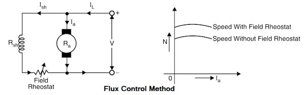
Flux control Method:-
Flux control method is based on the fact that by varying the flux A, the motor speed (N ∝ 1/φ) can be changed and hence the name flux control method. In this method, a variable resistance (known as silent field rheostat) is placed in series with shunt field winding as shown in Fig
The shunt field rheostat reduces the shunt field current Ish and hence the flux φ. Therefore, we can only raise the speed of the motor above the normal speed. Generally, this method permits to increase the speed in the ratio 3: 1. Wider speed ranges tend to produce.
Advantages
Easy and convenient method.
It is an inexpensive method since very little power is wasted in the shunt field rheostat due to the relatively small value of Ish.
The speed control exercised by this method is independent of the load on the machine.
Disadvantages
Only speeds higher than the normal speed can be obtained since the total field circuit resistance cannot be reduced below Rsh i.e the shunt field winding resistance.
(ii) There is a limit to the maximum speed obtainable by this method. It is because if the flux is too much weakened, commutation becomes poorer.
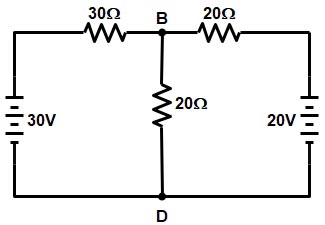
Ques 19. In the circuit shown in the figure the voltage at the node B with respect to Node D is calculated to be 15 V. Then the current in 30 Ω resistor will be
2.5 A
2A
10A
0.5 A✓
In the above circuit, node D is chosen as the reference node and the other three nodes are assumed to have voltages, Va, Vb and Vc with respect to node D
Ques 20. The type of single phase induction motor having the highest power factor at full load is
Capacitor run type✓
Capacitor start type
Shaded Pole Type
Split Phase Type
In capacitor run motor the starting winding remains connected all the times. There is no centrifugal switch in the capacitor run motor.
Because the capacitor remains in the circuit all the time a lower value capacitor is used the lower value capacitor has more phase shift as compared to the high-value capacitor, therefore, winding current is low.
Therefore the capacitor run motor has high running torque and improved power factor.
Ques 21. The following generating station has the minimum running cost:
Diesel Power station
Nuclear Power station
Hydroelectric Power station✓
Thermal Power station
The total generator operating cost includes^fuel, lassoer, and maintenance costs. For simplicity, fuel cost is the only one considered to be variable. The fuel cost is meaningful in case of thermal and nuclear stations, but for hydro stations, as electrical energy is generated by the use of water so the energy storage is ‘apparently free’, hence the operating cost of the hydro station is very cheap.