Ques 55. If the rotor EMF per phase at standstill is E2 and the motor is operating at a slip s, the generated rotor EMF per phase under running condition will be
S2E2
E2
SE2✓
E2/S
As we know that when the rotor is a standstill, s = 1, The value of e.m.f. induced in the rotor at standstill is maximum because the relative speed between the rotor and the revolving stator flux is maximum.
E2 = Rotor induced e.m.f. per phase on standstill condition
When the rotor starts running, the relative speed between it and the rotating stator flux is decreased Hence, the rotor induced e.m.f. which is directly proportional to this relative speed, is also decreased (and may disappear altogether if rotor speed were to become equal to the speed of stator flux).
Let this emf be, E2r
E2r = Rotor induced e.m.f. per phase in running condition
E2 ∝ Ns
E2r ∝ (Ns – N)
Dividing Both the equation
E2r/E2 = (Ns – N)/Ns
E2r = sE2
Ques 56. DC motor is recommended for the Locomotive drive is:
DC series Motor✓
DC long shunt compound Motor
DC Shunt Motor
DC short shunt compound Motor
In trains there are many compartments full of passengers & luggage, so during the starting, it requires high starting torque. DC series motor is used for the locomotive because it has very high starting torque and variable speed.
DC series motors will have a starting torque as high as 500% compared to normal operating torque
Ques 57. Two wattmeter method can be used to measure the total power delivered to:
Star connected with neutral loads
Delta connected load only
Star Connected load only
Star as well as Delta connected loads✓
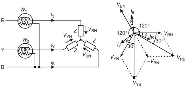
Power in a 3-phase three-wire system, with a balanced or unbalanced load, can be measured by using two wattmeters. The load may be star or delta connected. The current coils of the two wattmeters are connected in any of the two lines and the pressure coils are connected between these lines and the third line, as shown in Fig. The two-wattmeter method can be explained somewhat more clearly by considering a balanced load. In this case, we shall prove that power measured by the two wattmeters (i.e., the sum of two wattmeter readings) is equal to the total power consumed in a three-phase balanced load.
The connection diagram for a three-phase balanced load (connected in the star). Considering load to be an inductive one.The three voltages VRN, VYN, and VBN, are displaced by an angle of 120 degrees electrical as shown in the phasor diagram. The phase currents lag behind their respective phase voltages by an angle ϕ.
Ques 58. In case of a 3 phase induction motor, plugging is done by:
Starting the motor on load which is more than the rated load
Pulling the motor directly on line without a starter
Interchanging connections of any two phases of the stator for quick stopping✓
Locking of the rotor due to harmonics
It is known that the rotor of a polyphase induction motor develops torque in the same direction as the rotating magnetic field set up by the stator winding. Also if any two stator leads are reversed, the rotating magnetic field is also reversed. lf therefore, the pair of stator leads are reversed while a motor is rotating, torque is suddenly-produce opposite to the original direction of rotation. This reverse torque causes rotation in the opposite direction as soon as the motor stops, therefore provision must be made to disconnect the stator completely from the supply lines when the motor stops.
Hence Plugging in induction motor braking is applied by just reversing the supply phase sequence by interchanging connections of any two phases of the stator, we can attain plugging braking of an induction motor. Due to the reversal of phase sequence, the direction of the rotating magnetic field gets reversed. This produces a torque in the reverse direction and the motor tries to rotate in opposite direction.
This opposite flux acts as the brake and it slows down the motor. During plugging the slip is (2 – s), if the original slip of the running motor is s.
Note : The method can be applied to both squirrel cage as well as wound rotor induction motors.
Ques 59. Cables in power transmission line are provided with inter sheath to:
Minimize charging current
Minimize stress
Provide uniform stress distribution✓
Minimize high voltage
Grading
Grading is defined as the process of equalizing the stress in the dielectric of the cable. Generally, the electrical stress is maximum at the surface of the conductor or the innermost part of the conductor while it is minimum at the outermost sheath of the conductor.
The maximum voltage that can be safely applied to a cable depends upon gmax i.e., electrostatic stress at the conductor surface. For safe working of a cable having homogeneous dielectric, the strength of dielectric must be more than gmax. If a dielectric of high strength is used for a cable, it is used only near the conductor where stress is maximum. But as we move away from the conductor, the electrostatic stress decreases so the dielectric will be unnecessarily overstrong.
If the stress is equal to all the dielectric of the conductor, then the thickness of the conductor is reduced. But if the stress is maximum at any of the dielectrics then it increases the thickness of the cable due to which the cost of the cable also increases. There are two methods of grading the cable.
Capacitance Grading
Intersheath Grading
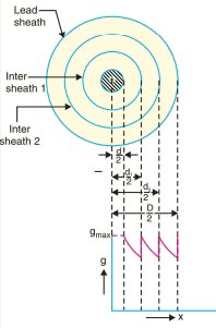
Intersheath Grading
In this method of cable grading, a homogeneous dielectric is used, but it is divided into various layers by placing metallic inters heaths between the core and lead sheath. The inter sheaths are held at suitable potentials which are in between the core potential and earth potential. This arrangement improves voltage distribution in the dielectric of the cable and consequently more uniform potential gradient is obtained. As there is a definite potential difference between the inner and outer layers of each inter sheath, therefore, each sheath can be treated like a homogeneous single core cable Maximum stress between the core and inner sheath is
Ques 60. The active and apparent powers of an inductive circuit are 60W and 100 VA respectively. The power factor of a circuit is
0.6 leading
0.6 lagging✓
0.5 lagging
0.75 lagging
Power factor = True power (watt)/Apparent Power(VA)
=60/100 = 0.6 Lagging
Since the load is inductive therefore power factor lagging.
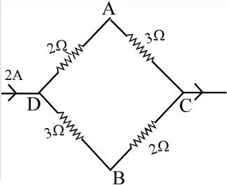
Ques 61. A current of 2A flows in the circuit shown in the figure. The potential difference VA – VB is
-1V
1V✓
2V
4V
As RDAC = RDBC = 5Ω hence current is equally divided among two branches joined in parallel.
VD – VA = Resistance x current = 2 x 1 = 2 volt
VD – VB = 3 x 1 = 3 volt
Hence (VD – VB) – (VD – VA) = 3 – 2 = 1 volt
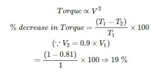
Ques 62. When the supply voltage to an induction motor is reduced by 10% the maximum torque will decrease approximately by
10%
20%✓
5%
40%
Ques 63. In an RLC series circuit the condition below the resonant frequency is:
Xc > XL✓
Xc + XL
Xc < XL
Xc = XL
REACTANCE
Reactance is the property of resisting or impeding the flow of alternating current or voltage in inductors (coils) and capacitors. It is part of the total opposition to the flow o. AC, also expressed in ohms, is extra to resistance.
There are two types of reactance:
Inductive reactance is the opposition in an inductive circuit (with a coil). When the apply voltage to an inductor a magnetic field is created that slows the current down while the voltage is allowed to build up freely. The amount of back emf depends on the rate of change of the current, in that, the larger its frequency, the larger will be the reverse current, so the effect decreases with a decrease in frequency.
Capacitive reactance exists in a capacitive circuit. and it decreases with an increase in frequency. Unlike inductive reactance, changes to the current occur before any changes to voltage-current now lead the voltage because when you first apply a voltage, the current will be at its highest value, but the voltage will be at the lowest.
Capacitive reactance is also measured in ohms and is inversely proportional to AC frequency, meaning that when the frequency is high reactance is low, and when it is low reactance is high. Capacitors, therefore, act as low resistance to high frequency and high resistance to low frequencies.
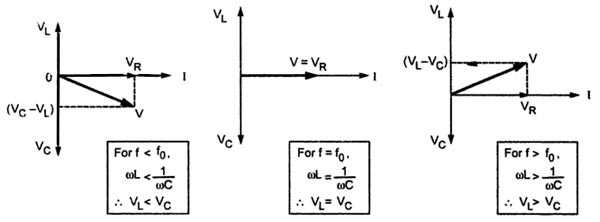
Fig. shows phasor diagrams for series RLC circuit for three different keeping values of both L, and C constant.
For any frequency f is lower than resonant frequency fo, inductive reactance is less than capacitive reactance. Hence the voltage drop VL is less than the voltage drop across the capacitor which is VC. So the current I leads the resultant supply voltage V and so the circuit behaves as a capacitive circuit at the frequencies which are less than fo.
At f = fo, the inductive reactance equals capacitive reactance. Hence the voltage VL is equal to VC. The two voltages cancel each other and the resultant voltage is same as the voltage VR. So the voltage and current are in phase. The circuit behaves as the pure resistive circuit at resonating frequency with unity power factor.
Similarly, for any frequency f higher than resonant frequency fo, capacitive reactance is very much less than inductive reactance. Hence the voltage drop VL is more than the voltage drop across the capacitor which is VC. So the current I lags the resultant supply voltage V and so the circuit behaves as an inductive circuit at the frequencies which are more than fo.
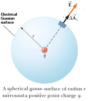
Ques 64. The total electric flux through any closed surface is equal to the amount of charge enclosed. The above statement is based on:
Gauss’s Law✓
Ampere’s Law
Maxwell’s Law
Coulomb’s Law
The total electric flux through any closed surface is equal to the amount of charge enclosed is termed as Gauss’s Law.
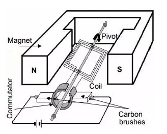
Ques 65. Brushes are provided in DC machine for
Smooth Rotation
Preventing sparking
Providing a Path for Flow of current✓
Reducing the losses
We know that commutator is connected to the armature so as the armature is rotating (to cut the flux in order to induce the EMF ) obviously commutator will also rotate with the armature.
So in order to collect the current, we should have something which is stationarily and can be fit into the commutator, and that is brushes.
The number of brushes depends on how much current we need to tap from the commutator.
Brushes are made up material like carbon, copper, and graphite.
Copper brushes are used for the machine designed for large current at low voltage.
Graphite and Carbon Graphite are self-lubricated therefore widely used.