DMRC JE Electrical 9th- April- 2018 Paper With Solution and Explanation

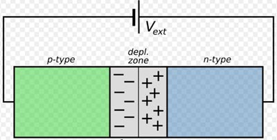
Ques 31. When reversed biased the width of the depletion layer in a PN junction diode is

  1. Remain same
  2. Increase
  3. Decrease
  4. Reduced to half

  • In a reverse-biased p-n junction diode, the positive terminal of the battery is connected to the n-type semiconductor material and the negative terminal of the battery is connected to the p-type semiconductor material.

img.16

  • In reverse biasing, free electrons and holes move away from the junction. Hence, increasing the width of the depletion layer. As the depletion layer increases, the potential barrier also increases.
  • The majority of charge carriers cannot move across the junction, hence current will not be allowed to flow across the diode. That is, on reverse biasing, the P-N junction diode acts as an insulator or as an Open switch.
  • An ideal diode acts as an open circuit under reverse bias conditions. A practical diode offers large but not infinite resistance under reverse bias conditions.
  • A diode conducts current when forward biased and blocks current when reverse biased.
  • The current flowing in the reverse-biased circuit due to the minority charge carrier is known as reverse current.


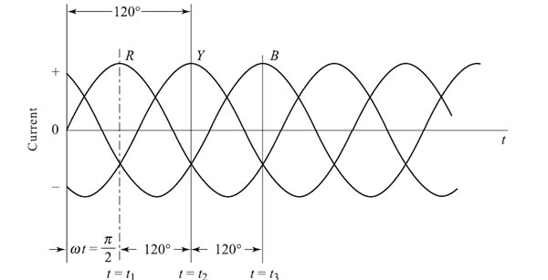
Ques 32. In case of induction Motor, synchronous speed is

  1. Speed of rotor
  2. Speed of stator flux
  3. Speed of stator
  4. Speed of rotor flux

  • While three-phase induction motors have wide applications as electrical machines, single-phase induction motors are mostly used for domestic applications.
  • More than 85% of the industrial motors in use today are in fact induction motors.
  • An induction motor is substantially a constant speed motor, similar to a dc shunt motor. It requires only a stator power supply unlike a synchronous motor which requires a 3-phase ac supply on the stator side and the excitation on the rotor side.
  • In an induction motor, torque is developed in the rotor due to induced currents that react with the main flux (stator). This is possible at speeds less than the synchronous speed, and for this reason, an induction motor is sometimes known as an asynchronous machine.
  • In any motor, torque is developed due to the interaction of two fluxes. In a dc motor, torque is developed due to the interaction of the main field flux and the armature flux, which are roughly at a space angle of 90° (neglecting the brush shift).
  • But in an induction motor, it is due to the interaction of the stator flux and the rotor flux, both moving with synchronous speed in space.
  • In a synchronous motor, torque is developed at the synchronous speed only due to the interaction of the stator flux and the rotor flux. This is due to the locking of the two fluxes and if the speed of the motor is lower than the synchronous speed, it leads to stability problems.

Consider the stator is wound for “p” pairs of poles, the resultant mmf rotates through “1/p” revolutions in one cycle. If f is the frequency of the stator supply, then in one second, the resultant mmf rotates through f/p revolutions. If n is the speed of rotation of the magnetic field in revolution per second, then n = f/p

i.e

f = nP———(1)

If P represents the total number of poles and N represents the speed in revolutions per minute RPM, then

p = P/2 and n = N/120———–(2)

From equation 1 & 2

f = PN ⁄ 120

The above expression is the same as the one derived from a simple emf generator generating a single phase emf. It follows that if the stator of an induction motor has the same number of poles as an alternator supplying 3-phase currents,as shown in fig. then the magnetic flux set up by the stator of the induction motor would at exactly the same speed as the poles of the alternator. Thus, the speed of the rotating magnetic flux is called the synchronous speed since it rotates exactly at the same speed as the poles.

screenshot 20180507 081704

Hence the synchronous speed of an induction motor is the speed of stator flux.


Ques 33. In a nuclear power station, the moderator is used to

  1. Accelerate the speed of the neutron
  2. Stop the Chain Reaction
  3. Absorb neutron
  4. Reduce the speed of Neutron

Moderator in Nuclear Power Station

In nuclear engineering, a neutron moderator is a medium that reduces the speed of fast neutrons, thereby turning them into thermal neutrons capable of sustaining a nuclear chain reaction involving uranium-235 or a similar fissile nuclide.

  • Neutrons produced from the fission process are ejected at one-twentieth of the speed of light and are termed fast neutrons.
  • These fast neutrons have more probability of being captured by fertile material U-238 and are far less effective in causing the fission of U-235.
  • U-238 absorbs the fast neutron to such an extent that the neutrons produced are absorbed before they can reach a U-235 nucleus.
  • Further, fast neutrons try to escape from the reactor core. To increase the chances of fission of U-235 (fissile material), either slow neutrons also called thermal neutrons are required or the percentage of U-235 is increased in the fuel.
  • Thus, to improve the utilization of these fast neutrons generated from the previous fission reaction, their speed is reduced by using moderators for the next fission reaction in the thermal reactor.
  • The lower velocity of neutrons provides a better opportunity for the fission of U-235 without enrichment. The absorption properties of U-238 are very much reduced when a slow neutron is used.
  • The function of moderators depends on the law of mechanics and neutrons are slowed down as a result of an elastic collision.
  • If a neutron collides with a nucleus of equal mass it will lose all its energy and comes to standstill.
  • If it collides with a nucleus of heavier mass there will be little change in its velocity and velocity will be reversed.
  • The speed of neutrons is reduced by colliding them with the nuclei of other material which is lighter, does not capture the neutrons but scatters them.
  • Each such collision causes a loss of energy, and the speed of the fast-moving neutrons is reduced. The best moderating materials are of low mass number and with no or little tendency to capture neutrons.
  • Graphite, light water (H2O), heavy water (D2O), and beryllium are generally used as moderators.


Ques 34. The induction motor is also known as

  1. Synchronous Motor
  2. Asynchronous Motor
  3. Repulsion Motor
  4. Commutator Motor

  • An induction motor is substantially a constant speed motor, similar to a dc shunt motor. It requires only a stator power supply unlike a synchronous motor which requires a 3-phase ac supply on the stator side and the excitation on the rotor side.
  • In an induction motor, torque is developed in the rotor due to induced currents that react with the main flux (stator). This is possible at speeds less than the synchronous speed, and for this reason, an induction motor is sometimes known as an asynchronous machine.


Ques 35. A moving coil instrument has full-scale deflection at 50 mV and 10 mA. The value of shunt resistance required to be connected to convert it into a (0 – 5A) ammeter is.

  1. 0.01Ω
  2. 0.1Ω
  3. 0.001Ω

Given

Full-scale Meter current Im = 10 mA = 0.01A

Full-scale Meter voltage Vm = 50 mV

Line current to be measured I = 5 A

Resistance of the instrument Rm = 50mV ⁄ 10mA =

Total Line current  = Shunt current + full Scale Meter current

∴ Shunt current Is

Is = I − Im = 5 − 0.01 = 4.99 A

Hence required shunt Resistance

S = ImRm ⁄ (Is)

= 0.01 × 5  ⁄  4.99 = 0.01Ω


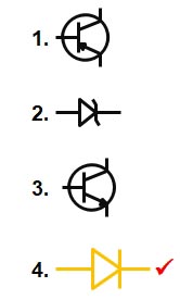
Ques 36. The schematic symbol for a PN junction diode is

img.30


Ques 37. An industrial consumer has daily load pattern of 4000 kW at 0.8 lag for 10 hrs and 1000 kW unity power factor for 16 Hrs. The daily load factor is

  1. 1.0
  2. 0.5
  3. 2.0
  4. 3.0

Load factor = Average load x time / Maximum Demand x time

= 4000 x 0.8 x 10 + 1000 x 1 x 16 ⁄ 4000 x 24

= 48000 ⁄ 96000 = 0.5


Ques 38. When forward biased the width of the depletion layer in a Pn junction diode

  1. Increase
  2. Decrease
  3. Doubles
  4. Remain same

A PN-junction diode is formed when a p-type semiconductor is fused to an n-type semiconductor creating a potential barrier voltage across the diode junction

Forward Biasing: If the positive terminal of an external battery is connected to the p-type and its negative terminal to the n-type of the PN junction then such a biasing is called forward biasing. Forward biasing reduces potential barriers and hence, depletion layer width decreases. The current is due to majority carries. Current is quite large when applied, with forward voltage. In forward biasing conditions, the PN junction acts as a Closed switch.

Diffiusion capacitance


  • An ideal diode acts as a short circuit under forward bias condition. A practical diode offers small but finite resistance under forward bias condition.


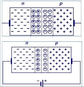
Ques 39. 1 Joule of electric energy equal to

  1. 1 Volt-ampere
  2. 1 watt. sec
  3. 1 watt/sec
  4. 1 watt

Electrical Energy

Electric energy is the total amount of electrical work done in an electrical circuit. Electric energy can also be defined as the product of power and time. The S.I Unit of Electrical- Energy is joule or watt-sec.

Electrical Energy

 ★The energy consumed by the circuit is said to be 1 joule or watt-sec when it utilizes the power of 1 watt for 1 second.


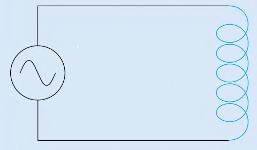
Ques 40. The inductive reactance of the circuit can also be stated as

  1. ωL
  2. 2πf
  3. πf
  4. 2fL

REACTANCE

Reactance is the property of resisting or impeding the flow of alternating current or voltage in inductors (coils) and capacitors. It is part of the total opposition to the flow o. AC, also expressed in ohms, is extra to resistance.

Inductive reactance is the opposition in an inductive circuit (with a coil). When the apply voltage to an inductor a magnetic field is created that slows the current down while the voltage is allowed to build up freely.

The amount of back emf depends on the rate of change of the current, in that, the larger its frequency, the larger will be the reverse current, so the effect decreases with a decrease in frequency.

img.5 1

The value of inductive reactance can be found in the formula.

Inductive reactance XL = 2πfL

Where: XL is the Inductive Reactance in Ohms, ƒ is the frequency in Hertz and L is the inductance of the coil in Henries.

We can also define inductive reactance in radians, where Omega, ω equals 2πƒ.

Now Inductive reactance XL = 2πfL = ωL …………(since angular frequency ω = 2πf)

Scroll to Top