
1. Which components of the symmetrical system have three phasors with equal magnitude but are displaced from each other by 120 degree having reverse phase sequence as compared to that of original?
- Zero sequence components
- Positive sequence components
- Negative sequence components
- Unity sequence components
- Negative sequence currents are produced because of the unbalanced currents in the power system.
- The flow of negative sequence currents in electrical machines (generators and motors) is undesirable as these currents generate high and possibly dangerous temperatures in a very short time.
- Phase current and voltage in the three-phase system can be represented in the form of three single-phase components.
Positive sequence components, Negative sequence components, and Zero sequence components.
Positive sequence currents exist during the balanced load condition.
Causes and effects of Negative Sequence Components:
The main cause of negative phase sequence components are:-
- Unbalanced loads in the system.
- Unbalanced system faults (line to ground faults, two-phase faults, three-line to ground faults, double line to ground faults).
- Open phases (open circuit faults).
Effects of Negative Sequence Components
- When the load on the generator becomes unbalanced, negative phase sequence currents flow.
- The negative sequence components produce a rotating magnetic field that rotates at synchronous speed in a direction opposite to the direction of the rotor field.
- Hence effectively the relative speed between the two is double the synchronous speed. Thus double frequency currents are induced in the rotor.
- This double-induced high-frequency current will raise the rotor temperature very high and damages the machine it operates continuously.
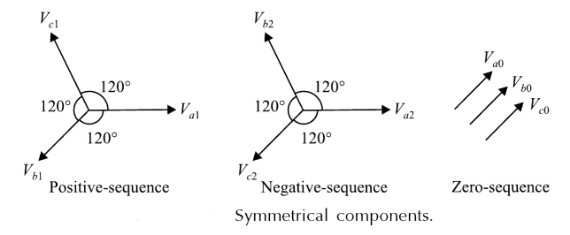
Positive sequence component: It represents three equal phasors, phase displaced by 120° and has phase sequence same as the original phasors.
Negative sequence component: It represents three equal phasors, phase displaced by 120° with each other and has phase sequence opposite to that of the original phasors.
Zero sequence component: It represents three equal and parallel phasors with zero-degree phase displacement.
2. In case of an unbalanced star-connected load supplied from an unbalanced 3-phase 3-wire system, load current will consist of:
- Only zero sequence component
- Only +ve sequence component
- Both +ve and –ve sequence component
- Only zero sequence component
PHASE SEQUENCE
The phase sequence of the phasors is the order in which they pass through a maximum. Thus phase ‘abc’ implies that the maximum occurs in the order a, b, c if ‘abc’ is taken as the positive ‘acb’ represents the negative phase sequence. It should be noted that for both positive and negative sequences, the direction of rotation of phase is taken to be anticlockwise. The positive sequence voltage is defined to have the phase sequence of the original system.
SYMMETRICAL COMPONENTS OF AN UNBALANCED THREE PHASE SYSTEM
According to Fortescue’s Theorem, three unbalanced phasors of a three-phase system can be resolved into three component sets of balanced phasors.
1. Positive sequence components.
2. Negative sequence components.
3. Zero sequence components.
Positive Sequence Components
A set of three phasors equal in magnitude, displaced each other by 120° in phase and having the same phase as the original phasors.
Unbalanced Star Load Supplied from Unbalanced Three-phase Three-wire System
In this case, line voltages and load currents will consist of only positive and negative-sequence components (but no zero-sequence component). But load voltages will consist of positive, negative, and zero-sequence components.
For a 3-phase, 3-wire star-connected system without a neutral wire, unbalanced loading may cause different voltage drops in three lines. Consequently, the three-phase voltages will be different both in magnitude as well as in phase, In such cases, the voltage of one phase may even exceed the line voltage. This may damage the equipment connected to the line due to over-voltage. For this reason, an unbalanced load is not normally used on a 3-phase, 3-wire system.
Zero sequence component:
It represents three equal and parallel phasors with zero-degree phase displacement. It is the set of three phasors equal in magnitude and all three phasors are in phase.
3. The _________ faults are due to short circuits in conductors.
- Series
- Parallel
- Series-Parallel
- Shunt
The most common and dangerous fault that occurs in a power system is the short-circuit or shunt fault. Such a fault involves a power conductor or conductors-to-ground or short- circuit between conductors and causes a flow of heavy current, called the short-circuit current, through the power system and equipment. It results in considerable damage to the equipment and interruption of supply to the consumers.
Short-circuit Fault
Power system equipment is required to work under unpredictable conditions, such as with a live conductor touching the ground (the short circuit problem) or lightning striking the conductors (the over voyage problem). Unter faulty conditions of the system healthy phase voltages may rise beyond the rated value, the faulty phase current may increase abnormally or both these anomalies may occur concurrently. These are undesirable effects that may lead to damage of costly equipment due to the breakdown of insulation.
A short circuit occurs when two points at different potentials are connected either with zero resistance (a dead short circuit) or with a substance of low resistance (a simple short circuit). A short-circuit current is several times higher than the rated current of the equipment. In a short circuit, heavy current flows through all parts of the system into the defective area or fault. This problem is of particular significance in the present-day inter-connected power systems. A fault may be designated either as a series or a shunt fault. While a series fault is due to the breakage of conductors, a shunt fault arises due to short circuit. Shunt faults are more serious than series faults, and many times sedes faults are converted to shunt faults. The excess MVA at the location of a fault is referred to as the fault level at that point.
4. Single phase to ground fault is a/an ______ fault.
- Symmetrical
- Unsymmetrical
- Any of the above
- None of the above
Types of Fault:-
Calculation of short-circuit currents gains importance in the design of protective switchgear like isolators, circuit breakers, short circuit current limiting reactors and the design of settings for protective relays. Faults are divided into two types:
- Symmetrical or balanced faults
- Unsymmetrical or unbalanced faults
Unsymmetrical Faults
The faults in the power system network which disturb the balanced condition of the network are known as unsymmetrical faults. The unsymmetrical faults are classified as the single line to ground faults (SLG), double line to ground faults (DLG 10%), and line to line faults (LL 15%). More than 90 % of faults that occur in a power system are single line to ground faults. The connection diagrams of different types of unsymmetrical faults are shown in Fig.
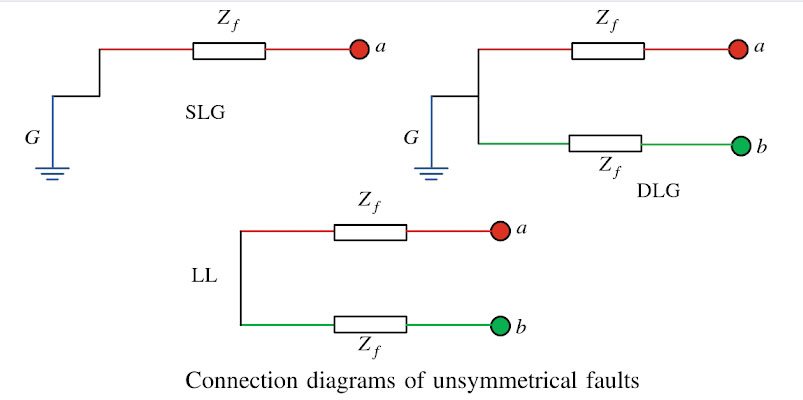
Single Line-to-Line Ground:- The single line of ground fault occurs when one conductor falls to the ground or contact the neutral conductor. The 70 – 80 percent of the fault in the power system is the single line-to-ground fault.
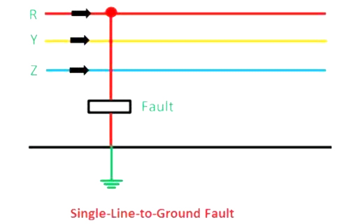
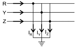
5. The given figure represents which of the following faults?
- Line-to-line fault
- Line-to-ground fault
- Symmetrical fault
- Double-line-to-ground fault
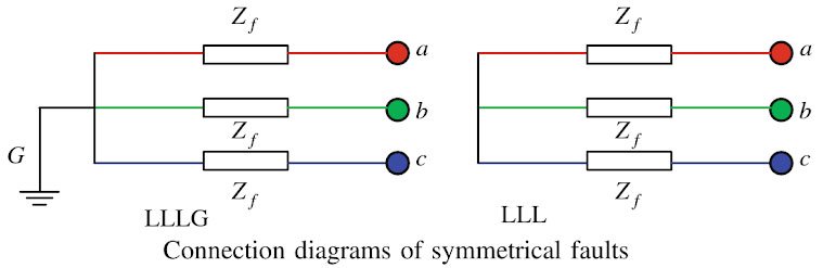
Symmetrical Fault
The symmetrical faults are often known as balanced faults. Balanced faults occur infrequently, but they are serious due to heavy fault levels. During these faulty conditions, symmetry (or balanced condition) may be observed in all three phases. In the case of balanced faults, all three transmission lines are affected equally, and the system remains in a balanced condition. These types of faults are rare in the power system, and it contributes 2 % to 5 % of the total fault. These faults are easy to analyze. The symmetrical faults are classified as three lines to ground fault (LLLG) and three lines fault (LLL). The connection diagrams of symmetrical faults are shown in Fig. If the fault impedance, Zf= 0, then the fault is known as a solid or bolted fault.
Due to symmetry, knowledge of the condition of one phase in a three-phase system is sufficient to estimate the condition of other phases. This simplifies short circuit calculations to a great extent as calculations are made on a single-phase, rather than on a 3-phase basis.
Different type of faults involved are:
Line to ground fault: It is the fault when a fault occurs on any one of the three lines through the ground.
Line-to-line fault: It is the fault when a short circuit occurs between the two lines.
Double-line-to-ground fault: It is the fault when a short circuit occurs between the two lines through the ground.
L- L- L-G (Three-phase line to the ground fault):- The three-phase line to ground fault includes all the three-phase of the system. The L L L G fault occurs between the three phases and the ground of the system. The probability of occurrence of such type of fault is nearly 2 to 3 percent.
From the given diagram in the question, we can observe that the fault occurred on all three lines.
Therefore, the given figure represents a symmetrical fault.
6. The zero sequence component of the unbalanced system of vector VA, VB, and VC is ______ of their vector sum.
- 1/3rd
- 1/4th
- 1/2
- 1/5th
Fortescue’s theorem states that an unbalanced system of n related phasors can be resolved into n balanced phasors called symmetrical components of the original unbalanced phasors.
For a three-phase system, the three unbalanced phasors can be resolved into three balanced phasors, The balanced or symmetrical components are:
- Positive-sequence components consisting of three phasors equal in magnitude, displaced from each other by 120° in phase, and having the same phase sequence as the original phasors.
- Negative-sequence components consisting of three phasors equal in magnitude, displaced from each other by 120° in phase, and having the phase sequence opposite to that of the original phasors.
- Zero-sequence components consisting of three phasors equal in magnitude and with zero phase displacement from each other.
Va = Va0 + Va1 + Va2
Vb = Vb0 + Vb1 + Vb2
Vc = Vc0 + Vc1 + Vc2
α = 1 ∠120°, α2 = 1 ∠240°, α3 = 1 ∠0°
1 + α + α2 = 0
Any phasor multiply by α operator rotates anticlockwise 120°.
Va = Va0 + Va1 + Va2
Vb = Vb0 + Vb1 + Vb2 = Va0 + α2Va1 + αVa2
Vc = Vc0 + Vc1 + Vc2 = Va0 + αVa1 + α2Va2
[katex]\left[ {\begin{array}{*{20}{c}} {{V_a}}\\ {{V_b}}\\ {{V_c}} \end{array}} \right] = \left[ {\begin{array}{*{20}{c}} 1&1&1\\ 1&{{\alpha ^2}}&\alpha \\ 1&\alpha &{{\alpha ^2}} \end{array}} \right]\left[ {\begin{array}{*{20}{c}} {{V_{a0}}}\\ {{V_{a1}}}\\ {{V_{a2}}} \end{array}} \right][/katex]
Symmetrical component of transfer matrix
[V]012 = [A]-1[V]abc
[katex]{V_{ab}} = 13[{V_a} + {V_b} + {V_c}][/katex]
Hence, the zero-sequence component of the unbalanced system of vector [katex]\overrightarrow {{V_A}} ,\:\overrightarrow {{V_B}} ,\:\overrightarrow {{V_C}}[/katex] is1/3rd of their vector sum.
7. A 3 phase generating station has two 15000 kVA generators connected in parallel each with 15% reactance. A symmetrical fault occurs at the generator bus. What will be the short circuit in MVA?
- 50 MVA
- 100 MVA
- 250 MVA
- 200 MVA
Short circuit MVA = Base MVA/ Zeq
Base MVA = 15 MVA
Two generators are in parallel, equivalent reactance = Zeq = 0.15/2 = 0.075
Short circuit MVA = 15/0.075 = 200 MVA
8.In power flow analysis for a voltage-controlled bus, which of the following is the unknown quantity?
- Real power
- Apparent Power
- Reactive power
- Base Power
Power Flow Analysis
In solving the power flow problem, four quantities associated with each bus are considered. These are voltage magnitude |V|, phase angle α), real power I;), and reactive power Q. Depending on the quantities specified at the bus these are classified as follows:
Slack bus: One of the buses is taken as the reference bus where the magnitude and phase angle of the voltage are specified. This bus is known as the slack bus or swing bus. It makes up the difference between the scheduled loads and generated power caused by the losses in the network.
Load bus: At these buses, the active and reactive power are specified. The unknown quantities are the magnitude and angle of bus voltages. These buses are also known as P-Q buses.
Generation bus: Also known as voltage-controlled bus or P-V bus. Here the voltage magnitude V and the real power P are known. The unknown parameters are voltage phase angle and reactive power Q.
Bus types for power flow analysis are shown in the table given below:
|
Bus type |
Specified variable |
Unknown variables |
|
Reference bus or slack bus |
| Vi |, δi |
Pi, Qi |
|
Generator bus or voltage-controlled bus or PV bus |
| Vi |, Pi |
δi, Qi |
|
Load bus or PQ bus |
Pi, Qi |
| Vi |, δi |
Where | V | = Magnitude of the voltage
δ = Load angle
P = Active power
Q= Reactive power
9. In a power system, each bus, or node is associated with how many quantities?
- 2
- 4
- 8
- 10
- In a power system, each bust, or node is associated with 4 quantities
- In a power system, each bus is associated with real power (P), reactive power (Q), bus voltage magnitude (|V|) and phase angle of bus voltage
- But each bus is specified with two quantities only and the remaining other two quantities to be unspecified.
10. A 22 kV, 400 MVA generator has a reactance of 0.3 pu. The value of reactance on the new base of 25 kV and 200 MVA will be:
- 0.16 pu
- 16 pu
- 0.116 pu
- 0.106 pu
[katex]p{u_{new}} = p{u_{old}}{\left( {\frac{{k{V_{old}}}}{{k{V_{new}}}}} \right)^2}\left( {\frac{{MV{A_{new}}}}{{MV{A_{old}}}}} \right)[/katex]
Where
kVold = old base value of voltage,
kVnew = New base value of voltage,
MVAold = Old base value of machine rating,
MVAnew = New base value of machine rating,
Given data
Old kV = 22 kV
New kV = 25 kV
MVA old = 400 MVA
MVA new = 200 MVA
Reactance old = 0.3 pu
Calculation:
[katex]p{u_{new}} = 0.3 \times {\left( {\frac{{22}}{{25}}} \right)^2} \times \left( {\frac{{200}}{{400}}} \right)[/katex]
⇒ punew = 0.116
