Corona loss can be minimized by controlling the following factors:
The frequency of supply: Corona loss increases as the supply frequency increases.
The radius of the conductors: Generally corona loss increases when decreasing the radius of the conductor. In order to prevent this, bundled or hollow large diameter conductors must be used.
The distance between the two conductors: To prevent corona spacing between the conductors must be increased.
Air Pressure: In hilly areas, the corona effect is more dominant due to reduced pressure.
Using Smooth conductor: Since corona loss is higher at sharp corners of the conductors, due to the presence of the highly non-uniform field, increasing the conductor radius as a whole can reduce the corona effect significantly. More the imperfections on the conductor surface more will be Corona.
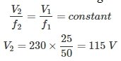
Ques 32. The low voltage winding of a 400/230 V, 1-phase, 50 Hz transformer is to be connected to a 25 Hz, the supply voltage should be
230 V
250 V
115 V
100 V
Answer.3. 115 V
Explanation:
To maintain the magnetizing current of the transformer at the same level the ratio of voltage to frequency must be the same.
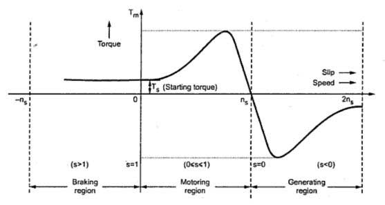
Ques 33. If an induction machine is run at above synchronous speed, it acts as
Synchronous Generator
Induction Generator
Induction motor
Synchronous Motor
Answer.2. Induction Generator
Explanation:
If an induction motor runs at above synchronous speed with supply connected to it, it works as an Induction generator.
To run an induction machine as the generator it slips must be less than zero that is negative slip (-1 < S < 0) it is also called as the regenerative action of an induction motor.
The supply here work simply as an exciter of the machine and instead of supplying any electrical energy it receives electric energy generated from the machine.
When the speed of the induction motor is increased above its rated speed, the e.m.f and slip of current frequency will develop in the rotor winding but with the opposite direction as compared to the direction when it’s operating below synchronous speed.
The torque slip characteristics of motoring and generating action is given below
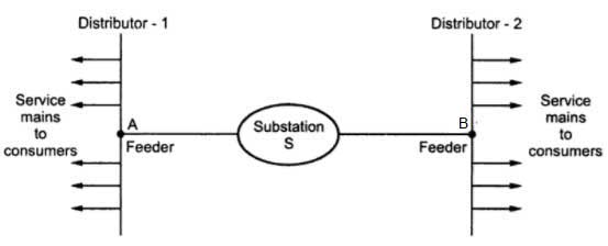
Ques 34. The main criterion for selection of the size of a distribution for a radial distribution system is
The station is located in the center of the load
Corona loss
Temperature loss
Capital Cost
Answer.1. The station is located in the center of the load
Explanation:
When the distributor is connected to the substation at only one end only with the help of the feeder then this system is called as Radial system.
In the radial system, if the fault occurs on the feeder or distributor then all the consumers get affected.
The system is useful only when the generation at the low voltage level and the substation are loaded at the center of the load.
Advantage of Radial System
Simple in operation
Low initial cost
Useful when the generation is low voltage
Preferred only when the station is located in the center of the load
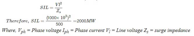
Ques 35. A voltage of 1000 kV is applied to an overhead line with its receiving end open. If the surge impedance of the line is 500 ohm, then the total surge power in the line is
2000 MW
1000 MW
10000 MW
200 MW
Answer.1. 2000 MW
Explanation:
Surge Impedance Loading is given as
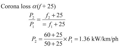
Ques 36. The corona loss on a particular system at 50 Hz is 1.2 kW/phase per km. The corona loss on the same system with supply frequency 60 Hz will be
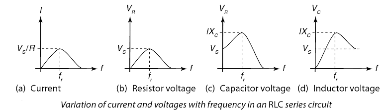
Capacitance: At frequencies below the resonance i.e fr, Xc > XL the current leads the source voltage and the circuit is totally capacitive. The phase angle decrease as the frequency reaches 0 degrees.
Inductive: At frequencies above the resonance i.e fr, XL > Xc the current lags the source voltage and the circuit is totally capacitive. The phase angle increases as the frequency approach 180 degrees.
Ques 38. For reducing tower footing resistance it is better to use
Chemical and ground rods only
Chemical and counterpoise only
Ground rod and counterpoise only
Chemical, ground rods and counterpoise
Answer.3. Ground rod and counterpoise only
Explanation:
Tower Footing Resistance
Tower footing resistance (Rt) is the resistance offered by the metal parts of the tower and the ground resistance and It is important for the protection against Surge Voltages.
Since the tower footing resistance depends upon the soil resistivity and critical breakdown gradient of the soil hence chemical treatment can be used this method requires regular checking of soil condition at each and every tower which are several miles apart hence it is very much time-consuming. Therefore we use Ground-Rod and counterpoise.
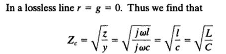
Ques 39. A lossless line terminated with its surge impedance has
Flat voltage profile
Transmission line angle is greater than the actual length of line
Transmission line angle is less than the actual length
Both 1 and 2
Answer.1. Flat Voltage profile
Explanation:
Lossless Line
For flat voltage profile system, all the voltage drop in the line are neglected therefore supply voltage (Vs) is equal to the Receiving end voltage (Vr) i.e Vs = Vr
The characteristic impedance of a lossless transmission line is purely real, with no reactive component. Energy supplied by a source at one end of such a line is transmitted through the line without being dissipated in the line itself.
Therefore lossless line terminated with its surge impedance has Flat Voltage profile.
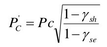
Ques 40. With 100 % inductive shunt compensation, the voltage profile is flat for
100 % loading on the line
50 % loading on the line
Zero loading of the line
Any of the above
Answer.3. Zero loading of the line
Explanation:
The virtual shunt impedance Loading is given as:
Where ϒsh is degree of Shunt compensation
ϒse is degree of Series compensation
The inductive shunt compensation increases the virtual surge impedance and decreases the virtual surge impedance loading of line.
If inductive shunt comp. is 100%, the virtual surge impedance becomes infinite and loading zero.