The main idea behind shunt compensation in a transmission line is to provide enough reactive power so that it can transmit power according to increase or decrease in load demand.
Thus during light load condition shunt compensator is able to minimize the line overvoltage.
During heavy load demand, shunt compensator is able to maintain appropriate voltage regulation.
Ques 22. The insulation of modern EHV and UHV lines is designed based on
Corona
Radio interface
Lightning voltage
Switching voltage
Answer.4. Switching Voltage
Explanation:
Switching Overvoltage
The amplitude of switching overvoltages is a key factor for designing the insulation of UHV equipment. The effect of different arresters needs to be studied, since installing arresters is an important way to suppress switching overvoltages in UHV transmission lines.
The most common temporary overvoltages occur in the healthy phases of a system during phase-to-earth faults.
Switching overvoltages appear in the power systems due to switching of load and/or fault currents, and they cannot be avoided.
Insulation Coordination is a series of steps used to select the dielectric strength of equipment in relation to the operating voltages and transient overvoltages which can appear on the system for which the equipment is intended.
Thus Insulation coordination is an art to decide the insulation level of the equipment.
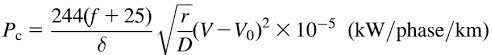
Ques 23. Corona loss can be reduced by the use of hollow conductors because
Current density is reduced
Eddy current in the conductor is eliminated
For a given cross-section, the radius of the conductor is increased
For better ventilation in the conductor
Answer.3. For a given cross-section, the radius of the conductor is increased
Explanation:
The size of the conductor and their spacing has a considerable effect on corona loss.
Corona loss is given by
Where, f = Supply frequency
δ = Air density factor
r = Radius of the conductor
D = Distance between the conductors
V = Operating voltage of the transmission line
Vo = Critical disruptive voltage
Corona loss increases with frequency. Corona loss increases very fast with an increase in system voltage since the loss is dependent on (V – Vo)2
Since the formation of corona on the conductor surface is dependent upon the maximum gradient, With an increase in the conductor size Diameter the potential gradient is decreased
By increasing conductor size the voltage at which corona occurs may be raised.
The hollow conductor increases the effective diameter without using any extra material. Therefore the corona effect gets reduced.
Ques 24. For a transmission line with negligible losses, the lagging reactive power (VAR) delivered at the receiving end, for a given receiving end voltage, is directly proportional to the
Line capacitive reactance
Line voltage drop
The square of the line voltage drop
Line inductive reactance
Answer.2. Line voltage drop
Explanation:
The VARs (lagging reactive power) delivered by a line is proportional to the line voltage drop and is independent of torque angle δ.
Hence, in a transmission system if, the lagging reactive power demand of the load is large, the voltage profile at that point tends to sag rather sharply.
To maintain the desired voltage profile, the VARs demand of the load must be met by employing condensers.
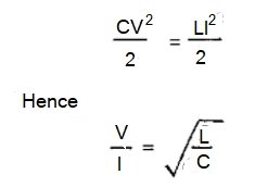
Ques 25. A long overhead transmission line is terminated by its characteristic impedance. Under this operating condition, the ratio of the voltage to the current at different points along the line will
Remain the same at all points
Remain same at the two ends, but be higher between the two ends being maximum at the center of the line
Progressively increase from the sending end to the receiving end
The progressively increase from the receiving end to the sending-end
Answer.1. Remain same at all points
Explanation:
The characteristic impedance or surge impedance (usually written Z0) of a uniform transmission line is the ratio of the amplitudes of voltage and current of a single wave propagating along the line.
Electrical energy on a length of a line equals to CV2/2 Where C = Capacitance V = magnitude of the travelling voltage wave
The magnetic energy of the length of the line is equal to LI2/2 Where L = Inductance of the line I = Magnitude of the traveling current wave
Hence in the surge impedance loading, the ratio of traveling voltage to the traveling current is determined by the ratio of L and C and in surge impedance, the voltage and current are in the same phase at any point along the line.
Ques 26. The function of the earth wire in an extra high voltage line is to
Prevent earth fault
Provide a safety measure of any high-flying object
Provide a shield to the phase conductors from direct lightning stroke
Provide mechanical strength to the towers
Answer.3. Provide a shield to the phase conductors from direct lightning stroke
Explanation:
Earth wire is also called the guard wire and it mainly protects lines from lightning.
If in case lightning struck then it carries the excessive current inrush to ground.
Its radius is much smaller than the actual transmission wire because as the resistance is inversely proportional to an area of cross-section and as the cross-section decreases, the resistance increases.
The increased resistance of earth wire is able to withstand high inrush of current caused due to lightning and it will safely guide this inrush into the ground.
It is placed above all the conductors mainly because if lightning struck then it will strike at the uppermost point in the line configuration and protect the actual conductors.
Ques 27. The time taken for a surge to travel a 600 km long overhead transmission line is
0.6s
1s
2s
0.002s
Answer.4. 0.002s
Explanation:
The time take for the surge to travel distance T =(x/v) s
Where x is the distance
v is the velocity of the surge which is equal to 3 x 10⁸ m/s
Distance given 600km which is equal to 6 x 10⁵ m
therefore, (6 x 10⁵/ 3 x 10⁸ )= 0.002 s
Ques 28. Whenever the conductors are dead-ended of there is a change in the direction of the transmission line, the insulator. used are the
Pin type
Strain Type
Shackle Type
Suspension type
Answer.2. Strain Type
Explanation:
Strain type insulators are used for handling the mechanical stress at the angle position of the line i.e Dead end, intermediate anchor tower, corner, sharp curve.
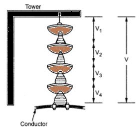
Ques 29. The non-uniform distribution of voltage across the units in a string of suspension type insulators is due to
The non-uniform distance between the cross-arm and the units
The non-uniform distance separation of the units and the tower body
The existence of stray capacitance between the metallic junctions of the units and the tower body
unequal self-capacitance of the units
Answer.3.The existence of stray capacitance between the metallic junctions of the units and the tower body
Explanation:
Voltage distribution Over a String Type Insulator
The non-uniform voltage distribution means a few units are stressed more while other units are lightly stressed. This can increase the flashover voltage or it can increase the number of disc units required to insulate a certain phase voltage.
Consider a string type insulators with 4 porcelain discs connected in series with the help of metal links.
The porcelain portion which is an insulator between the two metal fittings forms a self-capacitance.
Hence the whole string will consist of 4 such self-capacitors in series.
If only such self or mutual capacitors exist alone in series, the voltage and charging current across them would have been the same.
But in addition to the self-capacitance, there will be capacitance between each metal fitting and the earth which acts as a dielectric medium and called shunt capacitance.
And due to shunt capacitor, charging current does not remain the same and there is the non-uniform distribution of voltage across the units in a string of suspension type insulators.
Ques 30. The order of the sub-harmonic during SSR for 50 Hz normal frequency is
50/3 HZ
12 HZ
25 HZ
50 HZ
Answer.1. 50/3 Hz
Explanation:
Sub-synchronous resonance
Sub-synchronous resonance (SSR) is a phenomenon in which electrical energy is exchanged between generators and transmission systems below the nominal power frequency (50/60Hz)
The subsynchronous frequency is typically 1/3 of the fundamental frequency.
So for 50 Hz fundamental frequency, the subsynchronous frequency is 50/3 Hz.