
Ques.61. How should a fuse be installed in a circuit to ensure proper operation? (SSC 2016, Set-2)
- Parallel to the load
- Series with the load
- Either way possible
- At the ground point
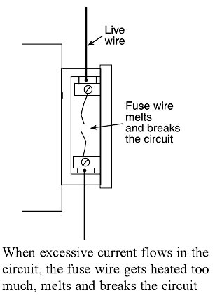
Answer.2. Series With the load Explanation:- Fuse is the current interrupting device that breaks or opens the circuit (in which it is inserted) by fusing the elements when the current in the circuit exceeds a certain value. Fuse is the simplest and cheapest device used for interrupting an electrical circuit under the condition of short-circuiting, or excessive overload, current magnitudes. A fuse is a safety device having a short length of a thin, tin-plated copper wire having the low melting point, which melts and breaks the circuit if the current exceeds a safe value. The thickness and length of the fuse wire depend on the maximum current allowed through the circuit. An electric fuse works on the heating effect of current. The fuse for protecting our domestic wiring is fitted just above our main switch on the switchboard. A fuse wire is connected in series in the electric circuits so that current flowing through the conductor to any load must also pass through the fuse. The main fuse in domestic wiring consists of a porcelain fuse holder H having two brass terminals T1 and T2 in it. This is connected to the live wire. The other part of the fuse is a removable fuse grip G which is also made of porcelain. The fuse grip has a fuse wire fixed in it. When a fuse grip is inserted in the fuse holder as shown in Figure, then the circuit of our domestic wiring is completed. So, under normal circumstances when the current is within the limit, then the fuse wire is intact and electric current is available in our wiring. When a short circuit takes place, or when overloading takes place, the current becomes large and her the fuse wire too much. Since the melting point of fuse wire is much lower than copper wires, the fuse wire melts and breaks the circuit as shown in Figure. When the fuse wire breaks, electricity supply automatically switched off before any damage can be done to the rest of the wiring (or the electric appliances being used). We will now give some important points about the fuse wire to be used in electrical circuits. First of all, we should know why we use a thin wire as a fuse wire and not a thick wire. We use a thin wire in a fuse because it has a much greater resistance than the rest of connecting wires. Due to its high resistance, the heating effect of current will be much more in the fuse wire than anywhere else in the circuit. This will melt the fuse wire whereas other wirings will remain safe. We should not use a thick wire as a fuse wire because it will have low resistance and hence it will not get heated to its melting point easily. The fuse wire usually made from tin-plated copper wire having the low melting point so that it may melt easily. A pure copper wire cannot be used as a fuse wire because it has a high melting point due to which it will not me easily when a short circuit takes place. Fuse wire is made with an alloy of lead and tin having the low melting point and low resistance (although the resistance of fuse wire is higher than that of electrical appliances). If due to any malfunction or fault, excessive current begins to flow through the circuit, the fuse wire immediately melts due to the heat generated by the flowing current. The circuit is broken and the excess current, which may damage equipment is prevented from flowing. It is used for Overload and for short-circuit protection in high voltage (upto 66 kV) and for low Voltage (upto 120 V – 240 V) installations/circuits. Characteristics of a fuse are:-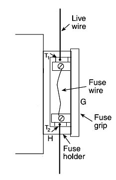
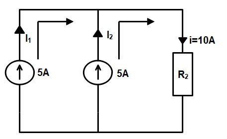
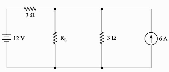
Ques.62. The circuit given below can be reduced to a single voltage source of if the Load resistance R2 = 1 ohm? (SSC 2016, Set-2)
- 15 V in series with R2
- 5 V in series with R2
- 10 V in series with R2
- 15 V in series with R2
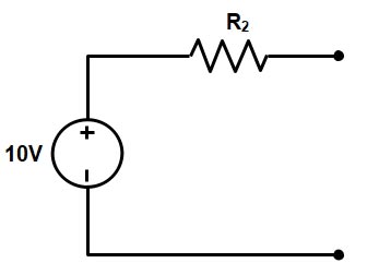
Answer.3. 10 V in series with R2 Explanation:- From the given figure the total current passing through the resistance R2 i.e 1 Ω is 10 A hence the voltage V V = R × I = 1 × 10 = 10 V Hence the voltage across the Resister R2 = 10 V so the above circuit can be reduced to a single source by connecting a voltage of 10 V and resistance of 1 Ω in series with each other as shown in the figure
Ques.63. The voltage supplied by the zinc-electrolyte cell shown in the figure below is _______ (SSC 2016, Set-2)
- Approximately 0.5 V
- Approximately 1.11 V
- Approximately 1.5 V
- Approximately 1.74 V
Answer.3. Approximately 1.5 V Explanation:- A simple cell consists of two strips, or electrodes, placed in a container that holds the electrolyte. A battery is formed when two or more cells are connected. The electrodes are the conductors by which the current leaves or returns to the electrolyte. In the simple cell described above, they are carbon and zinc strips placed in the electrolyte. Zinc contains an abundance of negatively charged atoms, and carbon has an abundance of positively charged atoms. When the plates of these materials are immersed in an electrolyte, chemical action between the two begins. In a dry cell, the electrodes are the carbon rod in the center and the zinc container in which the cell is assembled. The electrolyte is the solution that acts upon the electrodes that are placed in it. The electrolyte may be a salt, an acid, or an alkaline solution. In the simple voltaic cell and in the automobile storage battery, the electrolyte is in a liquid form; in the dry cell (see Figure 10.15), the electrolyte is a moist paste. A battery consists of two or more cells placed in a common container. The cells are connected in series, in parallel, or in some combination of series and parallel, depending on the amount of voltage and current required of the battery. BATTERY OPERATION The chemical reaction within a battery provides the voltage This occurs when a conductor is connected externally to the electrodes of a cell, causing electrons to flow under the influence of a difference in potential across the electrodes from the zinc (negative) through the external conductor to the carbon (positive), returning within the solution to the zinc. After a short period, the zinc will begin to waste away because of the acid. The voltage across the electrodes depends on the materials from which the electrodes are made and the composition of the solution. The difference of potential between the carbon and zinc electrodes in a dilute solution of sulfuric acid and water is about 1.5 volts. The current that a primary cell may deliver depends on the resistance of the entire circuit, including that of the cell itself The internal resistance of the primary cell depends on the size of the electrodes, the distance between them in the solution and the resistance of the solution. The larger the electrode and the closer together they are in solution (without touching the lower the internal resistance of the primary cell and the more current it is capable of supplying to the load. Note: When current flows through a cell, the zinc gradually dissolves in the solution and the acid is neutralized.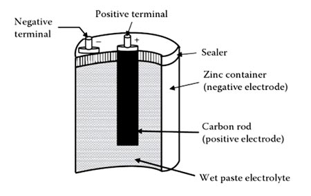
Ques.64. Which of the following circuit conditions does a metal oxide varistor (MOV) protect against? (SSC 2016, Set-2)
- High Current
- High Voltage
- High circuit Noise
- High crosstalk
Answer.2. High Voltage Explanation:- A varistor is a voltage-dependent resistor used as a device to protect delicate electrical circuits from sudden, drastic changes in voltage. The variation in the resistance they offer to the flow of current under varying voltage is the basis of their use. Varistor materials offer high resistance at low voltages and low resistance at high voltages. A varistor is coupled with the main electrical circuit in an alternative pathway. Normally when the voltage in the circuit is low this device does not conduct any current because they offer high resistance to the flow of current and hence current flows through the main circuit. But as soon as a drastic increase in voltage occurs, its resistance falls off and it allows most of the current to pass through, thus protecting the main circuit from damage. Varistors are used in voltage stabilizers and for motor speed control. There are two types of varistors Silicon Carbide Varistor or Carborundum crystal Varistor:- These varistors are made from silicon carbide mixed with a suitable ceramic binder material. The mixture la prefixed to the desired shape and then wintered (compressed under heat) under controlled conditions to the produced hard ceramic body. Silicon-carbide varistors have high power-handling capability and are used in high-voltage surge (lightning) arresters. The devices tend to draw considerable current in the normal state, and so they are commonly used in series with a gap that provides an open circuit until a surge occurs. This property makes silicon-carbide varistors unsatisfactory for low-voltage clamping operation. Newer zinc-oxide lightning arresters have better nonlinear characteristics and can be used without a gap. They are essentially crowbar devices but perform almost like clamping devices. Metal oxide Varistor:- They are made from the mixture of zinc oxide, bismuth oxide, and other powdered metals, which are pressed into the disc and then sintered above 1200°C At very low voltage they provide infinite resistance (open circuit) and when the applied voltage exceeds rated voltage they appear as a short circuit and thus protect, the component they shunt. Metal-oxide varistors (MOVs) is a solid-state device and is usually connected in parallel across the input power supply. Metal-oxide varistors (MOVs), the most common of the clamping devices, are available for use at a wide range of voltages and currents. The range of parameters includes: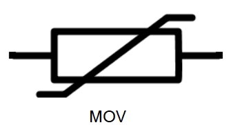
Ques.65. The frequency and time domain are related through (SSC 2016, Set-2)
- Laplace transform only
- Fourier integral only
- Laplace transform or Fourier integral
- Both Laplace transform and Fourier integral
Answer.4. Both Laplace transform and Fourier integral Explanation:- Frequency domain conversion: It is the analysis of mathematical functions or signals with respect to frequency, rather than time. Commonly, a time-domain graph shows signals over time, whereas a frequency domain graph shows how much of the signal lies within each given frequency band over a range of frequencies. The spectrum of frequency components is the frequency domain representation of the signal. A spectrum analyzer is a tool commonly used to visualize real-world signals in the frequency domain. A frequency domain representation can also include information on the phase shift that must be applied to each sinusoid to be able to recombine the frequency components to recover the original time signal. A given function or signal can be converted between the time and frequency domains with a pair of mathematical operators called a transform. The most common transforms between time and frequency are
Ques.66. _________ should be provided as the working space around the main switchboard, according to Indian Electricity Rule 51. (SSC 2016, Set-2)
- 0.523 m
- 1 m
- 0.638 m
- 0.814 m
Answer.2. 1m Explanation:- According to Indian Electricity Rule 51, every switchboard shall comply with the following provisions, namely:
Ques.67. A dominant wave is characterized by (SSC 2016, Set-2)
- Lowest attenuation
- Highest attenuation
- Lowest cut off wavelength
- Highest cut off wavelength
Answer.3. Lowest cut off wavelength Explanation:- Dominant Wave:- Dominant wave is the electromagnetic wave that has the lowest cutoff frequency in a given Uniconductor waveguide. As a wave-mode with lowest cut-off frequency is generally used for practical studies. Note:- Some Other Important Definition:- Waveguides: Waveguides are the hollow metallic tube of virtually any consistent cross-sectional shape through which an electromagnetic wave travels by reflection and not by conduction. Mode: Mode is a distinct field configuration obtained by solving Maxwell’s equation for the particular waveguide. Degenerate Mode: Two or more modes having the same cut-off frequency are said to be degenerate modes
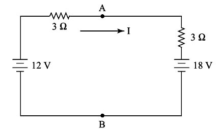
Ques.68. Determine the value of maximum power (in W) transferred from the source to the load in the circuit given below (SSC 2016, Set-2)
- 30
- 25
- 20
- 37.5
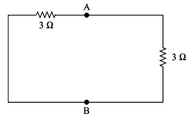
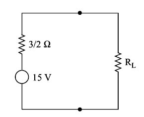
Answer.4. 37.5 Explanation:- Statement of the theorem: Maximum power transfer theorem is stated as “in a dc network maximum power will be consumed by the load or maximum power will be transferred from the source to the load when the load resistance becomes equal to the internal resistance of the network as viewed from the load terminals. Step-1: Converting the current source into the equivalent voltage source Step:2 Open circuit voltage terminal across A and B is calculated as Applying Kirchoff’s Voltage Law in the given circuit 12V − 3I − 3I − 18V = 0 −6V = 6I I = −1A The voltage across terminal A & B is V = 18 − 3 × 1 = 15V Step:-3 Equivalent Resistance Req across terminal A and B by short-circuiting the voltage source is = 3Ω || 3Ω = (3 x 3)/(3 + 3) Req = 3/2Ω Step:-4 Thevenin equivalent circuit across RL is For maximum Power transfer, RL = Rs = 1.5Ω Current I, = Vs ⁄ (RL + Rs) I = 15 ⁄ (1.5 + 1.5) I = 15 ⁄ 3 = 5A Maximum Power = I2RL = 52 × 1.5 = 37.5 W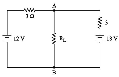
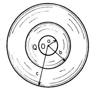
Ques.69. The electric field from ‘a’ to ‘b’ will be (SSC 2016, Set-2)
- Increasing
- Decreasing
- Remain the same
- Zero
Answer.2. Decreasing Explanation:- The electric field intensity at a point tat a distance R from Q) due to a point charge Q in free space can be obtained as E = Q/(4π εoR2) Where Q: Charge placed (in Coulumb) E ∝ 1/R2 Electric field intensity is inversely proportional to the distance between the charge b > a i.e Radius of b > Radius of a Therefore electric field at point ‘b’ will decrease from point ‘a’.
R: The distance between charge placed and point where the electric field is to be calculated
Ques.70. The leakage current must not be more than ____________ of maximum supply current (SSC 2016, Set-2)
- 1/1000
- 1/100
- 1/5000
- 1/150
Answer.3. 1/5000 Explanation:- Leakage current is an unwanted conductive path other than short circuit i.e under normal operating conditions. Ideally, the current leaking from the power supply unit should flow through the ground connection and into the installations of earth ground. As per the Indian electricity rules, the leakage current of installation should not exceed 1/5000 of the maximum supply-demand of the consumer.