
Ques.31. Which of the following is essential for the reciprocity theorem to be applicable? (SSC 2016, Set-1)
- Linearity
- Bilateralism
- No initial History
- All of the above
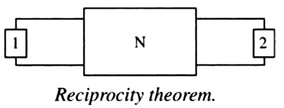
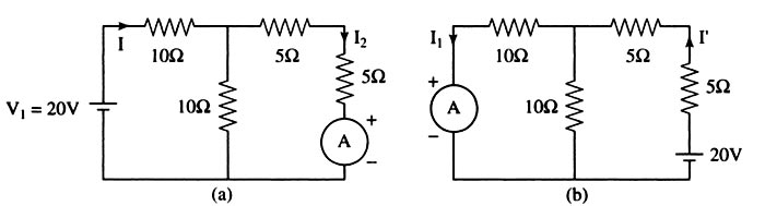
Answer.4. All of the above Explanation:- Linear circuit:- A linear circuit is an electric circuit in which circuit parameters (Resistance, inductance, capacitance, waveform, frequency, etc) are constant. In other words, a circuit whose parameters are not changed with respect to Current and Voltage is called Linear Circuit. Bilateral Circuit:- A circuit Chose characteristics are the same in either direction of the current flow is called a bilateral circuit. The electrical transmission line is an example of the bilateral circuit as it performs its functions equally Bell in both directions. Whereas, a diode is a unilateral element, unlike the bilateral element in which direction of flow of current affects circuit behavior. In forward bias, it has the least resistance and allows maximum current through it. In reverse bias, it offers high resistance to the flow of current. The reciprocity theorem is applicable to bilateral networks. A bilateral network is made up of bilateral elements. The theorem is stated as follows: The interchange of an ideal voltage source and an ideal ammeter in any passive, linear, bilateral network, will not change ammeter reading. Similarly, The interchange of an ideal current source and an ideal voltmeter in any passive, linear, bilateral circuit, will not change voltmeter reading. Consider Fig. Here, N is a passive linear network. Suppose an ideal voltage source, V1 volts, is inserted in branch 1 and it produces a current I2 in branch 2, then if the voltage source is inserted in branch 2, with V2 volts, and the current in branch 1, I1, is measured, it will satisfy the following relationship: V1/I2 = V2/I1 The reciprocity theorem cannot be applied when dependent sources are present. Consider the figure (a) and calculating the current I I = 20 ⁄ [10 + (10 || 10] = 1.333 A I2 = I/2 = 0.667A Now the source and the ammeter are interchanged as shown in the fig.b I” = 20 ⁄ [5+5 (10 || 10)] = 1.333 A I1 = I”/2 = 0.667A I2 = I1, Hence reciprocity theorem is verifiedReciprocity theorem
Verification of reciprocity theorem
Ques.32. Kirchoff’s current law is applicable to _____ (SSC 2016, Set-1)
- Electronic circuit
- Network junction
- Closed-loop in a network
- Electrical circuit
Answer.2. Network junction Explanation Kirchhoff’s Current Law (KCI ) or Kirchhoff’s Junction Rule. This law is based on the conservation of charge and may be stated as under: The algebraic sum of the currents meeting at a junction in an electrical circuit is zero. An algebraic sum is one in which the sign of the quantity is taken into account. For example, consider four conductors carrying currents I1, I2, I3, & I4 and meeting at point O as shown in Fig If we take the signs of currents flowing towards point O as positive, then currents flowing away from point O will be assigned a negative sign. Thus, applying Kirchhoff’s current law to the junction O we have, (I1) + ( I2) + (−I3) + (−I4) = 0 i.e., Sum of incoming currents = Sum of outgoing currents. Therefore, Kirchhoff’s current law may also be stated as under: The sum of currents flowing towards any junction in an electrical circuit is equal to the sum of currents flowing away from that junction. Kirchhoff’s current law is rightly called the junction rule. Kirchhoff’s current law is true because electric current is merely the flow of free electrons and they cannot accumulate at any point in the circuit. This is in accordance with the law of conservation of charge. Hence, Kirchhoff’s current law is based on the law of conservation of charge.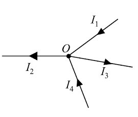
or
(I1) + ( I2) = (−I3) + (−I4)
Ques.33. In an R-L-C series circuit, during resonance, the impedance will be _____ (SSC 2016, Set-1)
- Maximum
- Zero
- Minimum
- Negative
Answer.3. Minimum Explanation In an RLC series circuit, the total impedance of the series LCR circuit is given as Z2 = R2 + (X1 – X2)2 where X1 is inductive reactance and X2 is capacitive reactance. At a particular frequency (resonant frequency), we find that X1 = X2 because the resonance of a series RLC circuit occurs when the inductive and capacitive reactances are equal in magnitude but cancel each other because they are 180 degrees apart in phase. Therefore, the phase angle between voltage and current is zero and the power factor is unity. Thus, at the resonant frequency, the net reactance is zero because of X1=X2. The circuit impedance Z becomes minimum and is equal to the resistance R. “Since the impedance is minimum, the current will be maximum”. Hence electrical resonance is said to take place in a series LCR circuit when the circuit allows maximum current for a given frequency of alternating supply at which capacitive reactance becomes equal to the inductive reactance.
Ques.34. For making capacitors, it is better to select a dielectric having_________ (SSC 2016, Set-1)
- Low permittivity
- High permittivity
- Permittivity equal to the air
- Zero permittivity
Answer.2. High Permittivity Explanation:- The dielectric constant refers to the material situated between the capacitor’s plates. No capacitor can maintain a charge on its plates unless the material or mixture of materials between them has some tendency to insulate. The dielectric constant εrrepresents the degree to which a substance or common mixture of substances tend to reduce the electric field between the plates. Hence, the capacitance is directly proportional to the dielectric constant, and the true quantitative definition of capacitance is: C = εrε0 A/d C is the capacitance, in farads; A is the area of overlap of the two plates, in square meters; εr is the relative static permittivity (sometimes called the dielectric constant) of the material between the plates (for a vacuum, εr = 1); ε0 is the electric constant, vacuum permittivity, permittivity of free space (ε0 ≈ 8.854×10⁻¹² F⋅m−1) d is the separation between the plates, in meters; From the above equation, the capacitance of the capacitor is directly proportional to the permittivity. If permittivity is high then the capacitance of the capacitor will be also high. Note:- When two conducting plates are brought closer and are separated by another plate that is made up of insulating material leads to the formation of the capacitor. The insulating material used in it is balled dielectric material. The main function of the dielectric material is to store electrical energy. Thus dielectric materials are used in capacitors. There are four types of capacitors available depending on the dielectric material used in them. 1. Capacitors with air and gases as dielectric:- Such capacitors are used in circuits where energy loss in them should be lower as well as the value of capacitance should be small. Thus, these types of capacitors are used in circuits where accuracy is the prime concern, for example, radio frequency circuits. 2. Capacitors with mineral oil as dielectric:- These capacitors give a large value of capacitance with a small amount of dielectric loss. 3. Capacitors with a combination of solid and liquid as dielectricsPaper, glass, mica, mineral oil, caster oil, etc. are used in these types of capacitors. Oil impregnated paper dielectric is used for making capacitors that should have a large value of capacitances. These types of capacitors are used in power distribution systems. 4. Capacitors with only solid as dielectric such as glass, mica, etc. These capacitors are used in laboratories. Mica has a high dielectric constant, high dielectric strength and low dielectric loss. Further, the dielectric constant of mica does not change much with temperature. Most of the capacitors are constructed as sealed components.
Ques.35. A current mirror can be used as an active load because______ (SSC 2016, Set-1)
- It has High A.C resistance
- It has Low A.C resistance
- Both High and low Resistance
- It has low D.C resistance
Answer.3. Both High and low Resistance Explanation:- A current mirror is a circuit designed to copy a current through one active device by controlling the current in another active device of a circuit, keeping the output current constant regardless of loading. Basically, a current mirror is a circuit that receives a current at the input and provides a copy of it at the output. This function can be theoretically modeled by a dependent current source, as mentioned before. Current mirrors are used to copy both DC and AC currents. In the applications where a current mirror is mainly employed to take part in the AC function of a circuit, its input and output resistances become important. Because the input and output signals are currents, an ideal current mirror is expected to have zero input resistance which helps to keep the input current constant regardless of drive conditions and infinite output resistance which helps to keep the output current constant regardless of load conditions.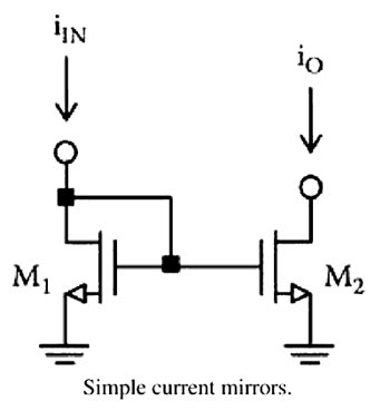
Ques.36. The angle of a series R-L-C circuit is leading if (SSC 2016, Set-1)
- XL = 0
- XC = 0
- XL > XC
- XC > XL
Answer.4. XC > XL Explanation When the load is inductive in nature the voltage leads the current by an angle φ. When the load is capacitive in nature the current leads the voltage by an angle φ. If the inductive reactance is greater than the capacitive reactance, i.e XL > XC the net reactance is inductive, then the RLC circuit has lagging phase angle and if the capacitive reactance is greater than the inductive reactance, i.e XC > XL the net reactance is capacitive then the RLC circuit have leading phase angle and if both inductive and capacitive are the same, i.e XL = XC then circuit will behave as purely resistive circuit.
Ques.37. If three 30 μF capacitors are connected in series, the net capacitance is (SSC 2016, Set-1)
- 90 μF
- 30 μF
- 10 μF
- 0 μF
Answer.3. 10 μF Explanation When the capacitor is connected in series then the total capacitance 1/C = 1/C1 + 1/C2 + 1/C3 1/C = 1/30 + 1/30 + 1/30 C = 10μF
Ques.38. Two heaters, rated at 1000 W, 250 V each are connected in series across a 250 V, 50 Hz ac mains. The total power drawn from the supply would be __________ watt. (SSC 2016, Set-1)
- 500
- 1000
- 250
- 750
Answer.1. 500 Explanation:- Given Power P = 1000 Watts Voltage V = 250 Watts Since power and voltage are same therefore heater resistance R1 = R2 = V2/P = 2502/1000 = 62.5Ω Since two resistance are connected in series their equivalent resistance R = R1 + R2 = 62.5 + 62.5 = 125Ω Now total power drawn is P = V2/R = 2502/125 = 500 watt
Ques.39. In which of the following, it is not desired to attain the condition of maximum power transfer? (SSC 2016, Set-1)
- Electronic circuit
- Communicational circuit
- Power system
- Computer circuit
Answer.3. Power System Explanation:- Electronic Circuit:-In electronic circuits, it is often desirable to transfer maximum power e.g (i) The signal power available at the receiving antenna is very small. It is very important to recover the maximum possible amount of signal power from the receiving antenna. (ii.) In the public address system, it is desired that maximum power is transferred from the amplifier to the speaker (i.e Ioad) in order to operate the speaker. To meet such situations in electronic circuits, we adjust the circuit for maximum power transfer. The technique is to make the load resistance (eg speaker) equal to the source (e.g amplifier) resistance. l he circuit is then said to be matched Power system:- Under the conditions of maximum power transfer, the efficiency is low (50%) and there is a greater voltage drop in the lines. In a power system, the goal is higher efficiency rather than maximum power. For these reasons, maximum power transfer is not desired in a power system.
Ques.40. In an R-L series circuit, the power factor P.F. is _______ (SSC 2016, Set-1)
- Leading
- Unity
- Zero
- Lagging
Answer.4. Lagging Explanation:- The RL series circuit is inductive in nature. The circuit consist of only inductance and resistance but not capacitance hence the power factor is lagging and current lags the voltage by an angle φ.