
Ques.51. The motor that is used for intermittent, high torque loads is
- DC Shunt Motor
- DC series Motor
- Differential Motor
- Cumulative Compound motor✓
The characteristics of cumulative compound motor lie between those of shunt and series motors. The series field provides a high starting torque and the shunt field prevents overrunning in the no-load condition. Class D motors are characterized by high starting torque, low starting current, and high operating slip. The rotor cage bars are made of high-resistance material such as brass instead of copper. The torque-speed characteristic is similar to that of a wound-rotor motor with some external resistance connected to the rotor circuit. The maximum torque occurs at a slip of 0.5 or higher. The full-load operating slip is high (8 to 15 percent), and therefore the running efficiency is low. The high losses in the rotor circuit require that the machine be large (and hence expensive) for a given power. These motors are suitable for driving intermittent loads requiring rapid acceleration and high-impact loads such as punch presses or shears. In the case of impact loads, a flywheel is fitted to the system. As the motor speed falls appreciably with load impact, the flywheel delivers some of its Kinetic energy during the impact. As we know that the in wound Induction motor we can achieve high starting torque by adding some external resistance. There it can be used for press and punches. These motors are used for drives where intermittent high load torque is required with the probability of the load being totally removed such as punch, press, shears, planning machine, conveyors, crushers, bulldozers, lid haulage gears, mine hoist, power fans, rolling mills, stamping press, and the large printing press.
Ques.52. The dummy coil in DC machines is used to ________
- Eliminate reactance voltage
- Eliminate armature reaction
- Bring about the mechanical balance of armature✓
- Eliminate harmonics developed in the machine
Ques.53. The major disadvantage of a feedback system may be
- Inaccuracy
- Inefficiency
- Unreliability
- Instability✓
Feedback is that property of a closed-loop system that permits the output (or some other controlled variable) to be compared with the input to the system (or input to some other internally situated component or subsystem) so that the appropriate control action may be formed as some function of the output and input. Feedback can be either negative or positive. In negative feedback, a portion of the output signal is subtracted from the input signal. In positive feedback, a portion of the output signal is added to the input signal. Negative feedback, for example, tends to maintain a constant value of amplifier voltage gain against variations in transistor parameters, supply voltages, and temperature. Positive feedback is used in the design of oscillators and in a number of other applications. Advantages of the Feedback System Disadvantages of Feedback Systems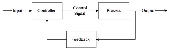
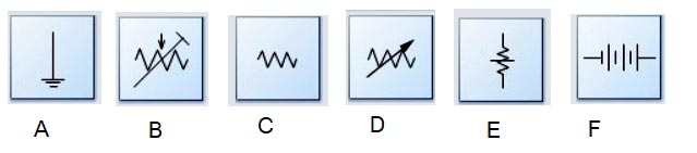
Ques.54. In the figures given below, which figure is the electrical symbol for a source of energy?
- Figure A
- Figure C
- Figure F✓
- Figure E
Figure F is the symbol of the battery and the battery is the source of energy. Note:- Figure A represents the Earth electrode Figure B represents Pre-set Potentiometer Figure C represents Resistor Figure D represents Variable Resistors Figure E represent Attenuator
Ques.55. In which of the following voltage sources, the movement of conductors in a magnetic field is used to produce voltage?
- Thermocouple
- Zinc Copper Element
- DC generator✓
- Transformer
Ques.56. What is the diameter of the GI pipe through which the earth wire needs to be taken out?
- 13 mm diameter✓
- 15 mm diameter
- 19 mm diameter
- 6 mm diameter
Earthing shall generally be carried out in accordance with the requirement of I.E. rules, 1956, as amended from time to time and the relevant regulation of the electricity supply.
and below the ground surface to the earth electrode to protect it against mechanical damage.
wiring system. All the earth wires run along the various sub-circuits shall be terminated and
looped firmly at the mainboard and from the mainboard, the main earth shall be taken to the earth
electrode. The loop earth wires used shall not be either less than 2.9 mm2 (14 SWG) or half of the size of the subcircuit conductor.
may not be in contact with all the different earth layers.
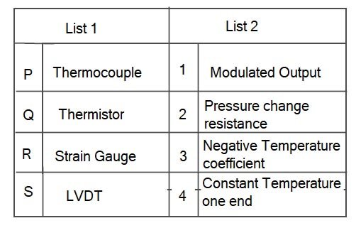
Ques.57. Match list 1 (transducer) with list 2 (characteristics) and select the correct answer using codes given below the lists.
- P-3; Q-2; R-4; S-1
- P-4; Q-3; R-2; S-1✓
- P-2; Q-1; R-4; S-3
- P-1; Q-2; R-3; S-4
Thermocouple When two dissimilar metal conductors are connected together to form a closed circuit and the two junctions are kept in different temperatures, thermal electromotive force (EMF) is generated in the circuit (Seebeck’s effect). Thermocouples make use of this so-called Peltier-Seebeck effect. Thus, when one end (cold junction) is kept constant at a certain temperature, normally at 0°C and the other end (measuring junction) is exposed to unknown temperature, the temperature at the latter end can be determined by measurement of EMF so generated. This combination of two dissimilar metal conductors is called ‘thermocouple’. Simply stated, a thermocouple is a device that converts thermal energy to electric energy. The amount of electric energy produced can be used to measure temperature. Thermistor Like RTD, Thermistor is also a temperature-sensitive resistor. A thermistor is an electronic component that exhibits a large change in resistance with a change in body temperature. Thermistors are highly sensitive to temperature variation; hence they are also called temperature-sensitive resistors. Thermistors are manufactured from metal oxide semiconductor material, which is encapsulated in a glass or epoxy bead. Thermistors also have a low thermal mass that results in fast response times but is limited by a small temperature range. If its resistance increases with temperature, it is said to have a positive temperature coefficient (PTC). If its resistance decreases with temperature, it is said to have a negative temperature coefficient (NTC). Strain Gauge Strain gauge is a passive type resistance pressure transducer whose electrical resistance changes when it is stretched or compressed. It can be attached to pressure sensed diaphragm. LINEAR VARIABLE DIFFERENTIAL TRANSFORMER (LVDT) This is the most widely used inductive transducer for translating linear motion into an electrical signal. As we know that displacement is a vector quantity representing a change in position of a body or a point with respect to a reference. It can be linear or angular (rotational) motion. With the help of the displacement transducer, many other quantities, such as force, stress, pressure, velocity, and acceleration can be found. LVDT gives modulated output. The LVDT gives reasonably high output and hence requires less amplification. The main electrical displacement transducers work on the principle of Variable resistance: transducer is a strain gauge. Variable inductance: transducer is a linear variable differential transformer Variable capacitance: transducer is a parallel plate capacitor with a variable gap Synchros and resolvers: used to measure angular displacement
Ques.58. For a prototype low pass filter, the series and shunt elements are respectively
- Capacitive and inductive
- Inductive and capacitive✓
- Series combination of capacitance and inductance
- Resistive and inductive
A filter is a circuit that is designed to pass a specified band of frequencies while attenuating all the signals outside that band. It is a frequency selective circuit. Low Pass Filter:- The low pass filter passes the low-frequency signal from input to output while it blocks high-frequency signals from the input. A low pass filter (even or odd orders based on a ladder network consists of shunt capacitors and series inductors that interconnect these shunt capacitors. No inductor is grounded. The load impedance/resistance is always grounded. For an even order low pass filter, the last reactive element is always an inductor, whereas, for an odd order filter, the least reactive element is always a capacitor. High Pass Filter:- In high pass filter, the filter rejects the frequencies which are less than cut-off frequencies ωo and it allows to pass the frequencies which are greater than ωo. The topology of a ladder network-based high pass filter is complementary to that of a ladder network-based low pass filter. Now all inductors are shunted, and series capacitors interconnect these shunt inductors. The load impedance/resistance is always grounded. Band Pass Filter:- A band-pass filter is one designed to pass signals with frequencies between two specified cut-off frequencies. A ladder network-based bandpass filter consists of alternating pairs of series and parallels connected capacitors and inductors. Each pair of parallel-connected capacitors and inductors is grounded. Each series-connected pair of capacitor and inductor interconnects two pairs of parallel-connected capacitor and inductor.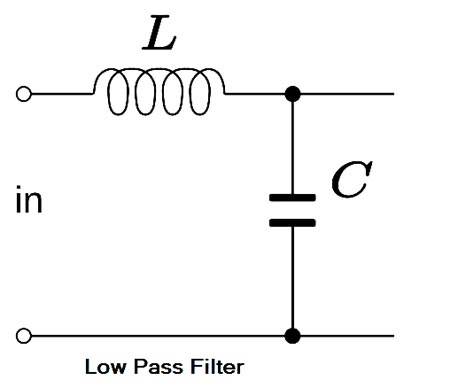
Ques.59. Kirchoff’s voltage law applies to circuits with
- Linear elements only
- Non-linear elements only
- Linear, non-linear, active and passive elements
- Linear, non-linear, active, passive time-variant as well as time-invariant element✓
Kirchhoff’s Voltage Law (KVL,) or Kirchhoff’s Loop Rule. This law is based on the conservation of energy and may be stated as under: In any closed electrical circuit or loop, the algebraic sum of all the electromotive force (e.m.f s) and voltage drops in resistors is equal to zero, i.e., in any closed circuit or loop. The algebraic sum of e.m.f s + Algebraic sum of the voltage drops = 0 The validity of Kirchhoff’s voltage law can be easily established by referring to the loop ABCDA shown in Fig. If we start from any point (say point A) in this closed circuit and go back to this point (i.e., point A) after going around the circuit, then there is no increase or decrease in potential. This means that the algebraic sum of the e.m.f.s of all the sources (here only one e.m.f. source is considered) met on the way plus the algebraic sum of the voltage drops in the resistances must be zero. Kirchhoff’s voltage law is based on the law of conservation of energy, i.e., the net change in the energy of a charge alter completing the closed path is zero. V1 + V2 − V = 0 or Kirchhoff’s voltage law is also called as loop rule. KVL and KCL and apply to any lumped electric circuit; it does not matter whether the circuit elements are linear, nonlinear, active, passive, time-varying, time-variant, etc. In other words, KVL and KCL are independent of the nature of the elements.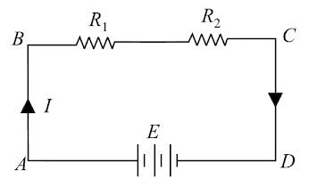
Ques.60. What will be the capacity of four capacitors of equal capacity ‘C’, when connected in series?
- 4C
- C/4✓
- 4/C
- 3/4C
When four capacitors of Capacitance C is connected in series the total capacitance 1/Ceq = 1/C + 1/C + 1/C + 1/C = 4/C Ceq = C/4