Ques 33. The resistance which is the property of opposing the current to flow depends upon its:
- The material or the specific resistance
- The area of the cross-section
- Its length and the temperature
- All of these✓
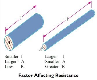
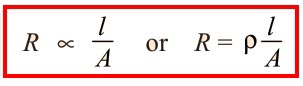
The resistance R offered by a conductor depends on the following factors : So for any given material at a certain given temperature, the resistance is given as where ρ is a constant and known as its specific resistance or resistivity. l = Length in Meter a = area of cross-section in m2 R = Resistance in Ohm Unit of Resistivity Specific Resistance depends only on temperature and material of the conductor but not on its dimensions of the conductor, on which resistance depends, and mechanical deformation such as stretching etc. As ρ depends only on the material of a conductor at a given temperature, hence it is a characteristic constant.Factors Affecting the Resistance
Ques 34. Which method can be used for the absolute measurement of resistances?
- Ohm’s law Method
- Wheat-stone bridge method
- Rayleigh Method
- Lorentz Method✓
Absolute instrument: Absolute instrument is an instrument that indicates the quantity to be measured in terms of the constant of the instrument (dimensions, turns, etc) and in order to find out the quantity in the practical units it is necessary to multiply such deflections with an instrument constant. No previous calibration or comparison is necessary in this case. The most common absolute instrument is the tangent galvanometer which gives the measured current in terms of the tangent of the deflected angle, the radius, and the number of turns of the galvanometer. Rayleigh’s current balance and Lorentz method of resistance measurement are examples of this class of instruments. Such instruments are rarely used (the use being merely confined within laboratories as standardizing instruments). Secondary instruments: Secondary instruments are those in which the value of the electrical quantity to be measured can be determined from the deflection of the instrument only when they have been Recalibrated by comparison with an absolute instrument. The deflection of the instrument gives directly the quantity to be measured. An example of the secondary instrument is
Ques 35. Galvanizing is the coating of
- Lead
- Chromium
- Brass
- Zinc✓
Ques 36. The eddy current losses in the transformer occur in:
- Primary winding
- Core✓
- Secondary Winding
- None of these
Eddy is a circular movement of water in a pond. Similarly, when it comes to electricity, eddies are the circular movement of currents. Eddy currents are circulating currents present in the magnetic core of the transformer. These currents occur due to the difference in magnetic flux in the core of the transformer. In the transformer, we provide alternating current in the primary which produces alternating flux in the core, this flux links with the secondary of the transformer and induces emf in the secondary. It may be possible that flux also links with some other conducting parts of the transformer such as the ferromagnetic core or iron body and induces local emf in these parts of the transformer which will cause a circulating current to flow in these parts causing heat loss. these currents are called eddy currents and this loss is called eddy current loss. Eddy current losses in the transformer is given by Eddy current losses = Ke × Bm2 × f2 × t2 Where Ke = Eddy’s current constant
t = thickness of the core
Ques 38. Which of the following is heaviest?
- Molecules✓
- Atom
- Electrons
- Protons
An atom is the smallest constituent unit of ordinary matter. Every atom is composed of a nucleus and one or more electrons bound to the nucleus. The nucleus is made of one or more protons and typically a similar number of neutrons. Electron(-vely charged), proton(+vely charged) and neutron (electrically neutral). The mass of electrons is the lowest whereas the mass of protons and neutrons is almost the same. mass of neutron = 1.67493 × 10⁻²⁷ kg So, the neutron is the heaviest among the rest of the particles. A molecule is an electrically neutral group of two or more atoms held together by chemical bonds. The molecular weight of a molecule is the sum of the atomic weights of its component atoms. Hence the molecule weight is the highest among all the given options.
mass of proton = 1.67262 × 10⁻²⁷ kg
mass of electron = 9.10939 × 10⁻³¹ kg
Ques 39. Star/delta starter is used in a:
- DC shunt Motor
- Three phase induction motor✓
- DC series
- All of these
Typically, three-phase motors will be started by instantly connecting the supply from the mains. In this case, the starting current is excessive and because of this, the starting torque of the motor is excessive. This torque will speed up the motor to attain its ultimate speed. This kind of starting is applicable for small motors i.e. motors that can be rated as much as 5HP. However, the same starting approach can’t be utilized for increased capability motors. The reason being defined under. In large motors, the starting current could be very excessive and if it is connected to the main supply, there might be an enormous voltage drop within the line. This voltage drop affects the behavior of different systems and other loads linked to the supply. The starting current of large three-phase induction motors will be as excessive as 6 times that of the maximum current (full load current). There are many types of Reduced Voltage Starters. Some of them are listed below. In star connection, line and phase currents are the same but the line voltage is √3 times the phase voltage. In the delta connection, line and phase voltages are the same but the line current is √3 times the phase current. However, the power in both connections is the same, that is √3VLIL cosφ. The starting current in an induction motor is proportional to the input voltage per phase to the motor. If VLL is the line to line voltage applied to the motor, IST ∝ ELL The voltage drop in the stator impedance is small compared to the applied voltage and can be neglected. VLL = ELL Therefore, the starting current in an induction motor is proportional to the supply voltage. If a reduced voltage is applied to the motor at starting, the starting current also will be reduced accordingly. While the starting current is reduced, causing a lesser voltage drop during starting, a lower starting current means a lower starting torque. The most popular and effective means of reduced voltage starting is achieved by means of star-delta starters. In this method, the motor windings are connected in star configuration during starting and then switched over to Delta once the machine has picked up sufficient speed (about 75% of the speed). By connecting the motor in the star configuration, the reduction in voltage corresponds to 1/√3 = 0.577. The reduction in starting current when compared to DOL starting is 33.3%. But the starting torque also gets reduced and this is a disadvantage. If this method is to be used, we must make sure that the load torque is not more than 50% of the rated torque.
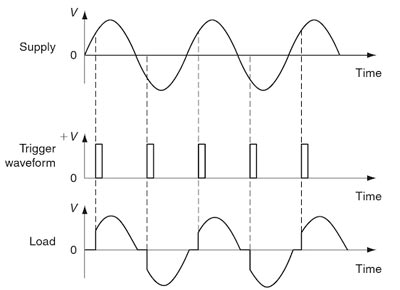
Ques 40. A triac is a
- Two terminal switch
- Two terminal Bilateral switch
- Three terminal unilateral switch
- Three terminal bidirectional switch✓
The TRIAC is a three-terminal semiconductor device for controlling current. It gains its name from the term TRIode for Alternating Current. A triac is a device that operates like an SCR for an AC circuit. The triac conducts during both halves of the AC waveform. This means that the output of a triac is AC, not DC as is the case with an SCR. The schematic symbol of a triac is shown in Figure. The triac is a three-terminal device. One terminal is called the gate, the terminal closest to the gate is called main terminal 1 (MT I), and the remaining terminal is called main terminal 2 (MT 2). The gate voltage must be the same polarity as MT2 to turn on the triac. The Device is triggered by applying the small gate pulse. The triac will continue to conduct until the current flowing through it decreases below its minimum holding current level.
Ques 41. Method of improving Power factor
- Static Capacitor
- Synchronous Condensor
- Use of Phase advancer
- All of these✓
Normally, the power factor of the whole load on a large generating station is in the region of 0.8 to 0.9. However, sometimes it is lower and in such cases In order to improve the power factor, some devices taking leading power should be connected in parallel with the load. This can be achieved by the following equipment A synchronous condenser is a synchronous motor running without the mechanical load. The Synchronous motor takes a leading current when over-excited and therefore behaves as a capacitor. When such a machine is connected in parallel with the supply, it takes a leading current which partly neutralizes the lagging reactive component of the load. Thus the power factor is improved. There are special commutator machines, which are used to improve the power factor of the induction motor. When the supply is given to the stator of an induction motor, it takes a lagging current. So, the induction motor has low lagging power factor. For compensating this lagging current, a phase advancer (mounted on the same shaft) is used. It supplies MMF to the rotor circuit at slip frequency. Note:- For more detail check SSC JE CONVENTIONAL PAPER 2017 QUES 5(D) : SSC JE CONVENTIONAL PAPER 2017 CAUSES OF LOW POWER FACTOR
Static Capacitor:-
Synchronous condenser
Phase Advancer:
Ques 42. One volt is same as
- One joule
- One coulomb
- One joule/coulomb✓
- One coulomb/joule
Volt is the electrical unit of voltage or potential difference (symbol: V). One Volt is defined as energy consumption of one joule per electric charge of one coulomb. 1V = 1J/C One volt is equal to the current of 1 amp times the resistance of 1 ohm: 1V = 1A ⋅ 1Ω
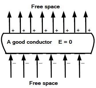
Ques 43. Inside a hollow spherical conductor:
- An electric field is zero✓
- Electric field constant
- Electric field changes with the magnitude of the charge given to the conductor
- Electric field changes with the distance from the center of the sphere
When the magnitude of the induced field becomes equal to that of the applied field, the net field intensity inside the conductor will become zero That is the Electric field due to the charges inside the conductor being directed opposite to the electric field outside which the field inside the conductor originated. Remember: The charges move in a conductor so as to kill the external field Consequently, no further movement of charges will take place. That is, the static condition will be reached after a brief transient period during which charges move to the surfaces. External field lines terminate on the bottom surface and emerge from the top surface, as shown in the figure. Since field intensity inside a good conductor is zero, the potential gradient, which is numerically equal to the field intensity, is also zero. Accordingly, the potential has the same value everywhere inside a good conductor.Why is the electric field inside a conductor zero?