Ques 55. In an A.C circuit V = 50 sin(ωt – 60°) & I = 10 cos(ωt), then the power factor of an A.C circuit will be
0.5 lag
0.5 lead
0.866 lag
0.866 lead✓
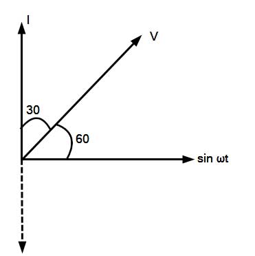
Given V = 50 sin(ωt – 60°) ———–1
& I = 10 cos(ωt)
Changing the “term” sin (90° – θ) = cosθ
Therefore I = 10 sin(90 – θ) or -10 sin(θ – 90)
or sin(180 + θ) = −sinθ
i = 10sin(θ + 180 – 90°) = 10sin90° ——–2
From the above two-equation, it is clear that current leads the voltage by 30°
Now drawing the phasor diagram taking sinωt as a reference
From the phasor diagram, it is clear that the current lead the voltage by 30 degree
The power factor is given as Cosθ = Cos30° = 0.866 leading
Ques 56. The relation between the frequency n, wavelength λ, and velocity of propagation V of the wave is:
V = nλ
λ = nv
n = v/λ✓
None of these
The “golden rule” for the relationship between the speed (v) of the wave, the wavelength (λ) and the period (T) or frequency ( f ). (recall that T = 1 / f, f = 1/T )
it follows from the speed = distance / time
the wave travels one wavelength in one period, so wave speed v = λ / T but since f = 1 / T, we have v = λ f or f = v/λ
this is the “Golden Rule” for waves
Ques 57. The bandwidth of AM signal is:
Directly proportional to the frequency of the modulation signal✓
Inversely Proportional to the frequency of the modulation signal
Not related to the frequency of the modulation signal
10 KHz
Amplitude Modulation, abbr. AM In AM radio transmission, the AUDIO signal is combined with a very high-frequency SINE WAVE called a CARRIER, in such a way that the strength or amplitude of the carrier is varied in exact response to the amplitude and FREQUENCY of the signal. This is called amplitude modulation of the carrier.
or
The process of varying, the amplitude of a relatively high-frequency carrier signal in proportional to the instantaneous value of the information (modulating) signal.
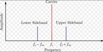
The band of frequency between (fc – fm) and fc is called Lower side-band frequency
Similarly, The band of frequency between fc & (fc – fm) is called Upper side-band frequency.
The bandwidth of the amplitude-modulated signal (BAM) is equal to the difference between the maximum upper-sideband frequency and the minimum lower-sideband frequency.
BAM = (fc +fm) – (fc – fm)
BAM = 2fm
where fm is the highest modulating frequency in Hz of the modulating signal.
The bandwidth of the amplitude-modulated signal is simply twice the highest modulating frequency present in the modulating signal.
The bandwidth of an audio signal (speech and music) is usually 5 kHz. Therefore,, AM radio station needs a bandwidth of 10 kHz.
AM stations are allowed carrier frequencies anywhere between 530 and 1700 kHz (1.7 MHz). However, each station’s carrier frequency must be separated from those on either side of it by at least 10 kHz (one AM bandwidth) to avoid interference.
Ques 58. The commonly used phase sequence is:
BRY
RYB✓
YBR
None of these
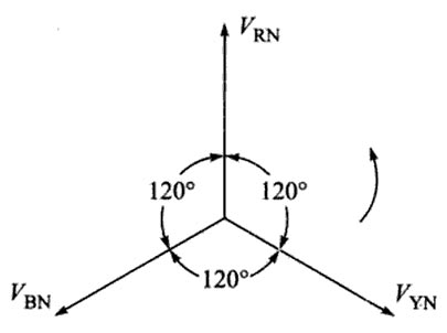
In a three-phase system, the order in which the voltages attain their maximum positive value is called Phase Sequence. The order in which the phase voltages of a 3-phase system attain their peak or maximum positive values is called the phase sequence of the system. The phase sequence RYB normally means that the red phase is followed by the yellow phase, which is followed by the blue phase. When the voltage of the red phase is at its positive maximum value, the voltage of the Y-phase will be 120° behind its positive maximum value, and that of B-phase 240° behind its positive maximum value as shown in fig.
Ques 59. Maxwell Bridge is used for the measurement of:
Frequency
Inductance✓
Resistance
Capacitance
A Maxwell bridge is a modification to a Wheatstone bridge used to measure an unknown inductance (usually of low Q value) in terms of calibrated resistance and inductance or resistance and capacitance. When the calibrated components are a parallel resistor and capacitor, the bridge is known as a Maxwell-Wien bridge.
Note:- Wien’s bridge is used for precision measurement of capacitance in terms of resistance and frequency. It was also used to measure audio frequencies.
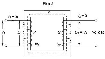
An open circuit test or no-load test on a transformer is performed to determine ‘no-load loss (core loss)’ and ‘no-load current I0‘ in the transformer.
At load, the primary current has two components: Shunt branch current & secondary current when referred to the primary side.
At no load, the secondary current becomes zero due to open-circuited at secondary.
As the transformer is open-circuited there is no output the current flowing will be no load current which is only a fraction of the full load current. For this reason, we can neglect the variable copper losses and whatever power is injected that may be considered core losses.
Therefore, only a shunt branch component is left which is used to magnetize the transformer coils. The current flowing in coils leads to winding losses. Hence, the current supplied by the source at no load is shunt branch current which is known as No Load Current.
No-load current has two components (a)Iron loss component (b) Magnetizing Component.
Iron loss component: It is the component of no-load current responsible for the resistive loss in the core.
Magnetizing Component: It is the component of no-load current responsible for hysteresis loss in the core
In this method, the secondary of the transformer is left open-circuited.
A wattmeter is connected to the primary.
An ammeter is connected in series with the primary winding. A voltmeter is optional since the applied voltage is the same as the voltmeter reading.
Rated voltage is applied at primary.
If the applied voltage is normal voltage then normal flux will be set up. Since iron loss is a function of applied voltage, normal iron loss will occur. Hence the iron loss is maximum at the rated voltage. This maximum iron loss is measured using the wattmeter.
Ques 61. The speed of the universal motor is:
Dependent on the frequency of supply
Proportional to the frequency of supply
Independent of the frequency of the supply✓
None of these
The universal motor is a type of electric motor that can operate on either AC or DC power. It is a commutated series-wound motor where the stator’s field coils are connected in series with the rotor windings through a commutator.
The universal motor operates similar to a typical direct motor (DC) motor, without a permanent magnet, except the stator and rotor coils are connected in series. This allows the motor to operate in DC as well as any frequency AC current. It is unique in that the rotation speed of the motor is independent of the input frequency.
Ques 62. In a 3-phase induction Motor, Maximum torque is obtained starting it:
Under normal conditions, the supply voltage is usually constant and the torque will be maximum when the denominator is minimum and these can only occur when R22/s = sX22
i.e when s = R2/X2
or R2 = sX2
Rotor reactance at running conditions is equal to slip time the rotor reactance at standstill.
i.e XR = sX2
Hence R2 = XR
Hence maximum torque occurs when the rotor resistance and rotor reactance are equal.
Ques 63. Break down test of transformer oil is done to measure;
Resistance of oil
Viscosity of oil
The dielectric strength of oil✓
Operating voltage of oil
The transformer oil (insulation oil) of voltage- and current transformers fulfills the purpose of insulating as well as cooling. Thus, the dielectric quality of transformer oil is essential to the secure operation of a transformer.
As transformer oil deteriorates through aging and moisture ingress, transformer oil should, depending on economics, transformer duty, and other factors, be tested periodically.
The dielectric strength of transformer oil is also known as the breakdown voltage of transformer oil or Breakdown voltage of transformer oil. Break down voltage is measured by observing at what voltage, sparking strands between two electrodes immersed in the oil, separated by a specific gap. The low value of BDV indicates the presence of moisture content and conducting substances in the oil.
Ques 64. Two transformers operating in parallel will share the load depending upon their:
Rating
Leakage Reactance
Losses
Per unit Impedance✓
If two transformers connected in parallel with similar per-unit impedances they will mostly share the load in the ration of their KVA ratings.And current carried by these transformers is inversely proportional to their internal impedance. Hence the impedance of the transformer running in parallel is inversely proportional to their KVA Rating Each transformer has a particular value of impedance which may be different from the other transformer i.e their resistance to reactance is different.