
Ques.51. The portion of the installed reserve kept in operable condition but not placed in service to supply the peak load is known as
- Cold reserve
- Hot reserve✓
- Operating reserve
- Spinning reserve
Neither one unit of large capacity generator nor a large number of small capacity generators is used to fulfill total demand at any time of the plant. A compromise is made between the two alternatives. So, a number of generating units of different capacities are used. Also, all units are not operated simultaneously. Types of the different units are given below. Types of the different Generating units are as given below. Reserve margin: It is the rated capacity in service minus actual loading on the generator.
Ques.52. For the production of induced e.m.f, the field system of an electric machine ____.
- Must be on the rotor
- Must be on the stator
- May be on rotor and stator✓
- None of the above
BASIC PRINCIPLES OF ELECTRICAL MACHINES In any machine, the currents in all the windings combine together to produce the resultant flux. The field system produces flux. Voltages are induced in the windings such as those of an armature. When the armature carries current, the interaction between the flux and the current produces torque. Current produced by the relative motion of stator/rotor conductor or magnet is called induced current, set up by an induced electromotive force or EMF. EMF is produced when a current-carrying conductor is placed in a rotating magnetic field. Where either field is rotating or conductor. These are the basic facts on which the action of the machine depends. The windings of the electrical machines are mainly of three types: TYPES OF ELECTRICAL MACHINES The type of a machine depends on how a particular type of combination of the above windings is used on the stator and the rotor. A synchronous machine has a coil winding and a polyphase winding. Generally, the polyphase winding is on the stator while the coil winding is on the rotor. The coil winding on the rotor produces a field and with the rotation of the rotor, this moves in space at the speed of the rotor. The voltage will be induced in the staler polyphase winding (three-phase). The magnitude of the voltage depends on the strength of the de field and the frequency corresponding to the speed of the rotor when driven as a generator. In the case of motor action, the polyphase winding is supplied with three-phase currents. This produces a rotating field in the air gap. This, when it reacts with the dc field produced by the current in the rotor, makes the machine run as a motor at synchronous speed. The construction of the field system may be on the stator or the rotor. A dc machine has a coil winding for the poles on the stationary part. This produces the stationary field in the space in the air gap due to dc in the field windings wound on the poles. The armature or the rotor has a commutator type of winding with stationary brushes for connecting to the external circuit. The machine can work as a motor or as a generator, depending on the current input to or output from the armature. An induction machine has a polyphase winding both on the stator and the rotor. The three-phase winding on the stator produces a rotating magnetic field. This is cut by the closed circuit of the rotor, thereby producing an induced voltage in the winding due to the transformer action. This produces a current in the winding which reacts with the flux to produce torque. The machine runs as an induction motor on the induction principle.
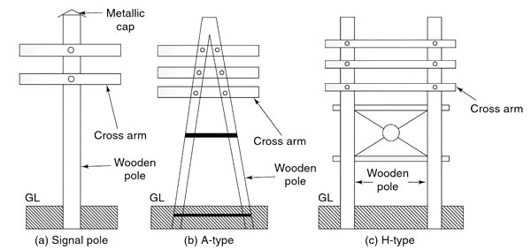
Ques.53. To prevent the decaying owing to snow and rain, the wooden poles are protected by _________ cap at the top.
A) Aluminum
B) Zinc
C) Cement
- Only A
- Only B
- Only C
- A, B & C✓
This is one of the simplest forms of the line support. Generally, wooden poles are used. They are cheap, easily available, and have good insulating properties. These poles must be straight, strong, and free from knots. The poles should be properly seasoned to prevent rapid decay because of crakes. An aluminum, zinc, or cement cap is used at the top of the wooden pole to prevent decay due to snow and rain. They are widely used for distribution purposes up to 22 kV and short spans (up to 60 metros). In cities where timber is easily available and the cost of transportation of steel tower is more, single and double pole structures either A or H type are widely used for overhead lines for 130 kV and for the span of 150 meters as shown in Fig. Wooden poles generally rot below the ground level and to prevent this preservative compounds such as creosote oil is used. Advantages of Wooden Poles Disadvantages of Wooden PolesWooden Poles:
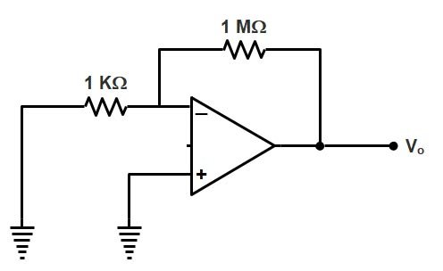
Ques.54. An OP-AMP has an offset voltage of 1 mV and is ideal in all other respects. If this OP AMP is used in the circuit shown in the figure, the output voltage will be approximately
- 2.5 V
- 3.4 V
- 1 V✓
- Zero
The op-amp is known as the differential amplifier because it amplifies the voltage difference of the inverting and non-inverting terminals. A third terminal represents the operational amplifier’s output port which can both sink and source either a voltage or a current. PROPERTIES OF THE IDEAL OPERATIONAL AMPLIFIER An ideal op-amp should have the following properties: Now coming back to the Question Input offset voltage(vio ) is the voltage that must be applied between input terminals of OPAMP to ensure zero output for zero input. vio = |v+ – v–| As non-inverting terminal of the given op-amp is connected to the ground. V+ = 0 As 1<<1000 therefore it can be neglected Vo = 1×103 ×1×10-3 = 1 V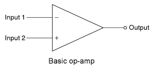
Vio = |0 – v–| = v–
V – = R1 /(R1 + RF )vo
Vo = (1+RF /R1 )v–
Vo = (1+RF /R1)vio
V0 = [1+(1×10⁶ )/(1×103 )]×1×10⁻³
Vo = [1+(1×10³ )]×1×10⁻³
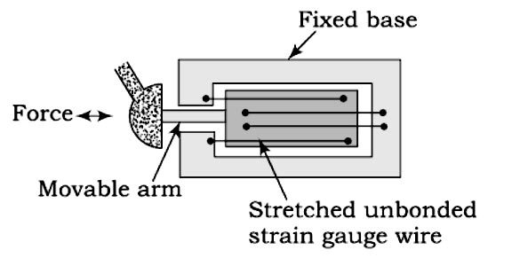
Ques.55. Unbonded strain gauges are _____.
- Exclusively used for stress analysis
- Exclusively used for transducer applications✓
- Used for unbounded strains only
- None of these
The strain is defined as the deformation of materials caused by the action of stress. A body subjected to external forces is in the condition of both stress and strain. Stress cannot be measured directly. As there is a relationship between stress and strain, the effect of stress can be shown by the measurement of the strain. Thus, the stress occurring in a body can be computed if sufficient strain information is available. The measurement helps in knowing better about any structure, whether it is strong enough for the purpose or it may fail in use.
Measurement of Strain Using Electrical Resistance Strain Gauges
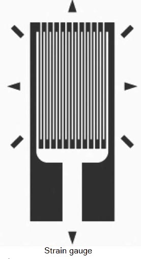
Strain gauges are made up of a long, thin strip of conductive material arranged in a zigzag manner. Load cells typically contain multiple strain gauges aligned and wired in a Wheatstone bridge circuit. When stress is applied to a strain gauge, the resistance of the strain gauge changes and unbalances the Wheatstone bridge, resulting in a signal output (voltage) that is proportional to the stress.
When a strain gauge is expanded or contracted by an external force, it experiences a change in electrical resistance. By bonding a strain gauge to the surface of a test specimen with an electrical insulator between them, the strain gauge changes dimension according to the expansion or contraction of the test specimen, resulting, in a change in resistance. This resistance is measured using the Wheatstone bridge which is the indication of the strain of the specimen at that point.
Types of Strain Gauges There are basically two types Of strain gauges unbonded and bonded.
Unbonded Resistance Strain Gauge: In general, the basic usage of the unbonded strain gauge is a displacement transducer. It can be constructed in a variety of configurations. The unbonded resistance strain gauge uses a strain-sensitive wire (or wires) with one end fixed and the other end attached to a movable element. Strain, induced on the wire by the displacement of the movable element, produces a change in resistance proportional to the displacement of the movable element. The unbonded strain gauge can measure the very small motion of the order of 50,μm and very small forces. The device is less robust than the bonded gauge and was developed at a time when the bounding technique was not reliable. With the advancement of improved bonding cement, unbonded wire strain gauges have become less common.
2. Bonded Resistance Strain Gauge: Bonded resistance strain gauge can be grouped into those that require an adhesive to fix the gauge so the pressure-sensing element (metal foil and strain sensitive wires) and those attached to the strain-sensing element by techniques that effectively make the strain gauge an integral part of the strain-sensing element (thin film and semiconductor).
Ques.56. The loss associated with the mechanical friction of a machine is called
- Eddy current Loss
- Mechanical Loss✓
- Hysteresis Loss
- Stray Load loss
In the rotating machine whether it is AC or DC machine the type of losses are almost the same The various losses in a d.c. the machine, whether it is a motor or a generator, is categorized amplified into three groups as: Copper losses are also called Electrical losses, winding losses or Ohmic losses. The copper losses are the losses taking place due to the current flowing in a winding. There are basically two windings in a d.c. machine namely armature winding and field winding. The copper losses are proportional to the square of the current flowing Through these winding; Thus the various copper losses can be given by Core losses are also known as iron losses or Magnetic losses. These Losses are constant and Independent of the load. They are induced in the machine due to hysteresis and eddy currents produced in the core produced when the magnetization is changing. They mainly occur in the armature teeth and core as also in the pole shoe. Hysteresis losses occur due to the reversal of the magnetization of the armature core. So, the hysteresis loss can be obtained as: Hysteresis Loss = Kh × BM1.67 × f × v watts where The eddy current loss exists due to eddy currents. When the armature core rotates, it cuts the magnetic flux and e.m.f. gets induced in the core. This induced e.m.f. sets up eddy currents which cause power loss. Ibis loss is given by, Eddy current losses = Ke × Bm2 × f2 × t2 Where Ke = Eddy current constant These losses are produced due to friction and windage (friction with air) caused by machine rotation. Hence, these are named mechanical losses. Some power is required to overcome mechanical friction and wind resistance at the shaft. They depend on the speed of the machine. The mechanical losses are also constant for a d.c. machine Bearing friction loss generally depends on the type of bearing used and on the viscosity of the lubricant. Brush friction loss is proportional to the contact area and the brush pressure. It also depends on other factors like the material of the brush and commutator, their polish condition, and the temperature at the contact surface. The magnetic and mechanical losses together are called stray losses. Stray load losses are losses that are produced in the machine when they are loaded. They cannot be considered with the main losses listed above. These losses include: (a) Additional core loss resulting from armature reaction distortion. (b) Copper loss due to short circuits produced in coils, segments, and brushes during commutation. (c) Copper loss due to non-uniform distribution of current in large-sized armature conductors. Stray load losses are very small in value and therefore, they are very difficult to calculate. In small machines, they can be neglected but for large machines, they are generally considered to be 1% of the output power in total.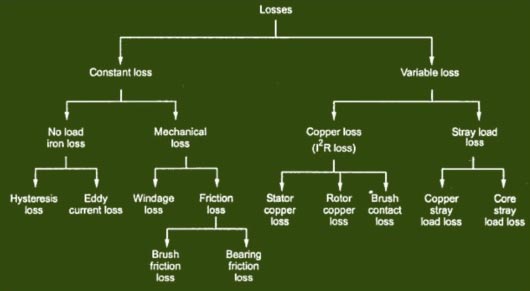
Copper Losses
Core Losses
Kh = Hysteresis constant depends upon the material
Bm = Maximum flux density
f = frequency
v = Volume of the core
t = thickness of the coreMechanical Losses
Stray Load Losses
Ques.57. What will be the voltage across Resistance R2 in the circuit given below?

- 14.35
- 13.33✓
- 15.45
- 12.33
The voltage across the resistance R2 can find out by voltage divider rule. Voltage Divider Rule (VDR) The voltage divider rule provides a useful formula to determine the voltage across any resistor when two or more resistors are connected in series with a voltage source. The voltage across the individual resistors can be given in terms of the supply voltage and the magnitude of individual resistances as follows I = V ⁄ (R1 + R2 + R3) V1 = I.R1 = V.R1 ⁄ (R1 + R2 + R3) Similarly V2 = I.R2 = V.R2 ⁄ (R1 + R2 + R3) Hence for the given question the voltage across the resistance R2 V2 = V.R2 ⁄ (R1 + R2) V2 = 20 × 40 ⁄ (20 + 40) V2 = 13.33 Volt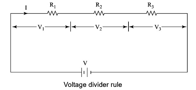
Ques.58. Fleming’s left-hand rule is used to find
- The polarity of the magnetic pole
- The direction of flux in a solenoid
- The direction of the magnetic field due to a current-carrying conductor in a magnetic field
- The direction of the force on a current-carrying conductor in a magnetic field✓
Force on a straight conductor carrying current placed in a magnetic field can be found by using Fleming’s left-hand rule. The forefinger represents the direction of the magnetic field, the thumb represents the direction of motion of the conductor, and the middle finger Ives the direction of the current.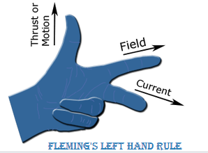
Ques.59. In a pure inductive circuit
- Current leads voltage by 90°
- Current lags voltage by 90°✓
- Current and voltage are in the same phase
- Any of the above
In a purely inductive circuit, the rate of change of current is opposed by the reactance of the coil, and the effect of this opposition is to make the current lag behind the applied voltage or be out of phase by 90°. The waveforms of current and voltage in a purely inductive circuit are shown in Fig. The current lags the voltage by 90°, as V has reached its maximum at point A when the current is zero at point B.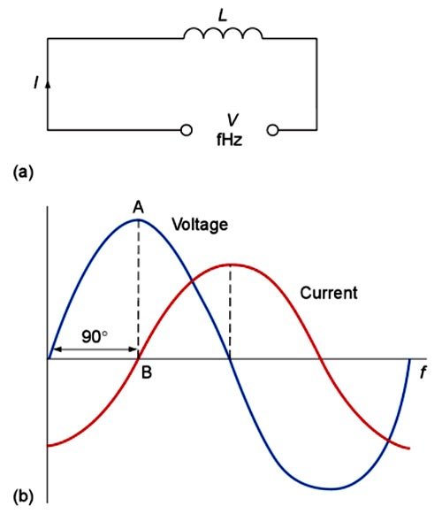
Ques.60. During discharge of a battery
- The voltage of the cell increases
- The voltage of the cell decreases✓
- The voltage remains same
- None of the above
Battery cycle and depth of discharge One discharge and charge period are referred to as a battery cycle. A major factor affecting battery life is the depth of discharge i.e. how much the battery is discharged and how often. The depth of discharge of a battery is a measure in the percentage of the amount of energy that can be removed from a battery during a cycle. Limiting the depth of discharge will make the battery last longer. If discharged beyond its recommended depth of discharge, the life of a battery will be considerably reduced. As the rate of discharge is increased, the cell terminal voltage, that is, the voltage at the output terminals of the cell drops because the internal resistance results in voltage drops within the cell due to the flow of current from the cell. These losses result in increased internal heating within the cell and reduced available energy. It is suggested that lead-acid batteries not be discharged beyond 80%, even if the battery is designed for deep discharge. Lead-acid batteries that are deeply discharged may suffer from a permanent loss of capacity due to sulphation, acid dilution, and a greater tendency for freezing. The fully charged lead-acid cell has 2.25 Volts. The 80% of this voltage is nearly 1.8 Volts.