Cranes for foundries, steelworks, and power stations generally require creep speeds on hoist motion for accurate load spotting. Cranes for material handling plants should be designed for higher operating speeds and duty cycles than any general workshop cranes. For steelworks, cranes must be selected to operate round the clock with higher operating speeds and low creep speed.
The classification of various types of cranes is mainly based on the following factors:
(i) Nature of the work it has to perform, e.g. handling of hot ladles, for transport of
ingots, for the handling of raw materials, etc.
(ii) The duty factor: This is the time it has to work compared to the total working period of the shop and the frequency of starting the crane. In a steel plant, they may be divided into 4 groups:
(a)Light-duty cranes (15% duty factor), e.g. cranes for compressor plant, refrigeration plant, power plant, Automobile workshop, etc. The electrical switching on the operation of light-duty cranes is 60 Per Hour.
(b) Medium-duty cranes (25% duty factor), e.g. handling materials in auxiliary and repair shops. The electrical switching on the operation of light-duty cranes is 120 Per Hour.
(c) Heavy-duty cranes (40% duty factor): The cranes of foundries, forging shops, cast houses, production Ime cranes. The electrical switching on the operation of light-duty cranes is 240 Per Hour.
(d) Continuous duty cranes (above 40% duty factor): These are for the major part of the production line: cranes for bulk material handling, soaking pit cranes, charging cranes. The electrical switching on the operation of light-duty cranes is 300 to 720 Per Hour.
Ques.92. In an induction motor, if the rotor resistance is equal to stand-still reactance then the maximum torque is
Maximum starting torque is obtained when the slip is equal to the ratio between the rotor resistance (R2) and the rotor inductive reactance (X2). This slip is also known as slip at maximum torque, labeled as Sm.
Ques.93. Which among these is a method of wiring?
A) Joint box B) Tee system C) Loop in system
Only A
Only B
Only C
A, B, & C✓
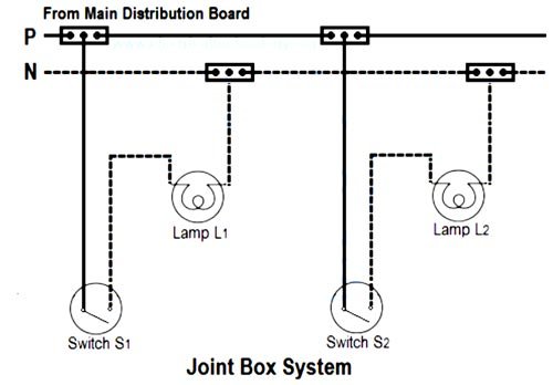
Joint box method or Tee method
The joint box is often a 4-terminal type, one box being needed for each light and its switch and situated about midway between them. From the joint box, one length of twin and earth PVC sheathed cable is run to the Light and another length to the switch.
This method of wiring doesn’t consume too much cables size. This method is suitable for temporary installations and is cheap.
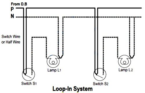
The looped method
This is one of the most widely used methods of wiring within the electrical installation industry. A PVC sheathed cable (phase-neutral and CPC) supplies each ceiling outlet point on your lighting circuit. From each point, another cable provides electricity to each control switch. Lamps and other appliances are connected in parallel so that each of the appliances can be controlled individually.
There are many advantages to using this method:
Ease of wiring – all connections are made 60m one level.
Easy to fault find – no flooring or inspection traps lo lifts
Can be added too without prior knowledge of where joint boxes are placed.
The disadvantage of this type of wiring is Looping – switches and lamp holders are usually difficult.
With the joint box system, the cable from the consumer unit runs to a series of joint boxes instead of to loop-in ceiling roses.
Ques.94. A minimum-phase system with no zeros has a phase-angle of – 270 ° at the gain crossover frequency. The system is
Stable
Unstable✓
Conditionally stable
Marginally stable
Gain margin and phase margin
Phase margin and gain margin are the measures of closed-loop control system stability. They are
Gain margin
Gain margin is defined as the amount of change in open-loop gain needed to make a closed-loop system unstable. The gain margin is the difference between 0 dB and the gain at the phase cross-over frequency that gives a phase of —180°.
The gain margin is defined as the number of decibels by which the system gain must be increased in order to cause the amplitude ratio to reach 1.0 (0 dB) at the frequency for which the phase angle first crosses−180 deg with a negative slope. At a gain margin of (0 dB), the system is marginally stable.
Phase margin
Phase margin is defined as the amount of change in the open-loop phase needed to make a closed-loop system unstable. The phase margin is also defined as 180 deg + phase angle for the frequency at which the system gain is 1.0; this point is called the gain crossover frequency. If the phase margin is positive, the system is stable; if it is negative, the system is unstable; and, if it is zero, the system is marginally stable.
Phase Margin = 180 + φ
where φ is the phase angle at the frequency where the magnitude crosses 0 dB
Now coming back to the question φ = – 270 °
Phase margin = 180° + (– 270 °)
Phase margin = −90°
Since the phase margin is negative hence the system is unstable.
Ques.95. In a common emitter amplifier, the function of the emitter bypass capacitor
Provide a low resistance path for the AC signals✓
Provide high resistance path for the AC signals
Act as a low resistance path for the DC signal
Provide short circuit path for the DC signal
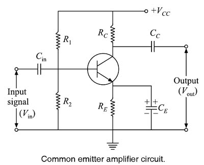
Common emitter (CE) amplifier is widely used in audio frequency applications in radio and television receivers. It provides current, voltage and power gains. For the proper functioning of an amplifier, the transistor must be biased in the active region where the base current has complete control over the collector current. Thus a small increase in the base current results in a relatively large increase in the collector current and a small decrease in the base current is followed by a large decrease in the collector current.
As shown in Figure along with the transistor there are various RC components used to work transistor as an amplifier. The functions of these components are as follows:
1. Biasing Circuit: Resistance R1, R2, and RE form the voltage divider biasing circuit for the CE amplifier. It sets the proper operating point and necessary biasing for the CE amplifier.
2. Input Capacitor Cin: This capacitor couples the signal to the base of the transistor. It blocks any dc component present in the signal and passes only the A.C signal for amplification. Because of this biasing conditions are maintained constant.
3. Emitter Bypass Capacitor CE: A capacitor is connected in parallel across the emitter resistor RE called emitter bypass capacitor CE. The purpose of the bypass capacitor CE is to bypass the signal current to the ground. The ac signal (feedback voltage) developed across the emitter resistor RE is bypassed through the capacitor CE. Thus the gain of the amplifier increases, Since it provides an easy path to the ac emitter current and allows it to pass on instead of flowing through emitter resistor RE, hence the name emitter bypass capacitor.
If this capacitor is not put in the circuit, A.C emitter current will flow through RE causing an AC voltage drop across it. This voltage will produce a feedback effect and thereby reduce the output voltage. Thus, for proper amplification, an emitter bypass capacitor CE is essential.
The value of this capacitor is nearly 100 μF. However, if an amplifier is required to handle more than one frequency (i.e. composite frequency signal), then the value of the emitter bypass capacitor must be chosen that provides adequate bypassing for the lowest of all the frequencies. Then it will also be a good bypass for all the higher frequencies.
As a design guideline, we make the reactance of the capacitance CE at the lowest frequency not more than one-tenth the value of RE.
4. Output Coupling Capacitor Cc: The coupling capacitor Cc couples the output of the amplifier to the load or to the next stage of the amplifier. It blocks dc and passes Only the AC part of the amplified signal.
Ques.96. If the capacitor of a single-phase motor is short-circuited, the motor will
Start normally
Not start at all✓
Start with jerk
Start and then stop
If the capacitor of the single-phase induction motor is a short circuit then auxiliary winding will act as an open circuit because capacitive reactance will become infinite of auxiliary winding.
XC = 1/2πfC
If C = 0 then Xc = ∞
So there will be no phase difference between main and auxiliary winding magnetic fields and motor starting torque will not produce. That’s why the motor will not run.
When the capacitor is short-circuited high inrush current will flow in the winding which may burn the starting winding of a single-phase induction motor.
Ques.97. Reluctance offered by the magnetic circuit depends upon
Length of the magnetic flux path
Nature of magnetic material
The cross-sectional area of the material
All of the above✓
RELUCTANCE
Flux in a magnetic circuit also depends on the opposition that the circuit presents to it. Reluctance (RM), is the opposition a magnetic circuit offers to the formation of magnetic flux.
The opposition depends on the dimensions of the core and the material of which it is made. As the resistance of a wire, reluctance is directly proportional to length (L) and inversely proportional to cross-sectional area (A). In equation form,
RM = L/( µo µrA) (Ampere-Weber)
The unit of Reluctance is Ampere-Weber or A/Wb
Where,
l: length of wire µo: absolute permeability µr: relative permeability of the material a: area of cross-section
Ques.98. The flow of electrons in the circuit constitutes
E.M.F
Magnetic charge
Electric current✓
None of the above
The flow of electrons in the circuit constitutes Electric current.
The concept of current and Electromotive force
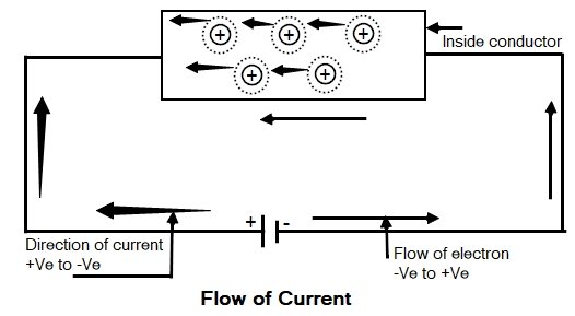
Consider a conductor which has large numbers of free electrons moving in a random direction. Now when we apply an external source to the conductor, then all free electrons drift along the conductor in a particular direction. The direction of the electrons will depend upon how the external source is applied to the conductor.
Hence the electrical source required to drift the free electron in a particular direction in a given conductor is called an electrical Electromotive Force.
As we know that the free electrons are negatively charged, when the external source is applied (such as the cell) then free electrons get attracted by the positive of the cell connection. Therefore the electrons get aligned in a particular direction under the influence of an electromagnetic force.
An ion is an electrically charged particle produced by either removing electrons from a neutral atom to give a positive ion or adding electrons to a neutral atom to give a negative ion. When an ion is formed, the number of protons does not change.
When the free electron gets dragged towards positive from an atom it becomes the positively charged ion. Such a positive ion drags a free electron from the next atom. This process repeats from atom to atom along the conductor. So there is the flow of electrons from negative to positive of the cell. This movement of electrons is called an electric current. The movement of electrons is always from negative to positive whereas the movement of current is assumed as positive to negative.
Relation between Charge and Current
The flow of electrons is called an electric current hence the current can be measured by the number of electrons passing through the material per second. In other words, the rate of flow of charge per unit time is called current. Current is measured in coulombs per second and one coulomb per second is called Ampere.
The relation between current and charge can be given as
I = Q/T Ampere
I = Average current flowing
Q = Total charge Transform
T = Time required for transfer of charge
Direction OF Current
In a source, the Direction of current is from lower potential to higher Potential while in an element the direction of current is from higher potential to lower potential.
Ques.99. In a parallel circuit operating with a source of 30 V AC, designed to carry a total current of 6 A, what happens to the protection device (fuse) when the resistance suddenly changes to 2Ω?
There is no change
It closes
It opens✓
It shorts to ground
When 30V AC source is carrying 6A the resistance of the path
ROLD= 30 /6 = 5Ω
New Resistance
RNEW = 2Ω
As resistance decreases the current in the circuit will increase and the fuse gets open-circuited to protect the equipment from overcurrent.
Ques.100. Generally, an electrolytic capacitor is made to provide
Fixed capacitance
Variable capacitance
Low capacitance
The large value of capacitance✓
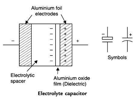
Electrolytic Capacitors
Electrolytic capacitors are generally used when very large capacitance values are required. Here, instead of using a very thin metallic film layer for one of the electrodes, a semi-liquid electrolyte solution in the form of jelly or paste is used which serves as the second electrode (usually the cathode).
The dielectric is a very thin layer of oxide that is grown electrochemically in production with the thickness of the film being Less than ten microns. This insulating layer is so thin that it is possible to make large value capacitors of a small size. The majority of electrolytic types of capacitors are polarized, that is the voltage applied to the capacitor terminals must be of the correct polarity as an incorrect polarization will break down the insulating oxide layer and permanent damage may result.
Electrolytic capacitors are generally used in D.C. power supply circuits to help reduce the ripple voltage or for coupling and decoupling applications. Electrolytic capacitors are most commonly based on either aluminum or tantalum electrode materials.
The metal electrode materials are processed so that they have a very high surface area, which results in high capacitance. In the case of aluminum electrolytic capacitors, the positive electrode (anode in a capacitor) starts as a thin foil that has been etched to create a large number of tunnels.
The tantalum and electrolytic capacitors have ratings of 6, 10. 12. 15. 20. 25, 35, 50. 75, 100V and higher.
For SSC JE 2018 SET-1 Electrical paper with complete solutionClick Here
For SSC JE 2018 SET-2 Electrical paper with complete solutionClick Here
For SSC JE 2018 SET-3 Electrical paper with complete solutionClick Here
For SSC JE 2018 SET-4 Electrical paper with complete solutionClick Here
For SSC JE 2018 SET-5 Electrical paper with complete solutionClick Here
For SSC JE 2018 SET-6 Electrical paper with complete solutionClick Here
For SSC JE 2017 Electrical paper with complete solutionClick Here
For SSC JE 2015 Electrical paper with complete solutionClick Here
For SSC JE 2014 (Evening shift) Electrical paper with complete solutionClick Here
For SSC JE 2014 (Morning shift) Electrical paper with complete solution Click Here
For SSC JE 2013 Electrical paper with complete solutionClick Here
For SSC JE 2012 Electrical paper with complete solutionClick Here
For SSC JE 2011 Electrical paper with complete solution Click Here
For SSC JE 2010 Electrical paper with complete solution Click Here
For SSC JE 2009 Electrical paper with complete solution Click Here