Ques.61. Arc blow is a welding defect that is encountered in
- Arc welding using A.C current✓
- Arc welding using D.C current
- Gas welding
- Thermit welding
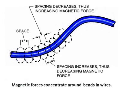
When electrons flow, they create lines of magnetic force that circle around the path of flow. These lines of magnetic force are referred to as magnetic lines of flux. They space themselves evenly along a current-carrying wire. If the wire is bent, the flux lines on one side are compressed together, and those on the other side are stretched out, as shown in Figure. The unevenly spaced flux lines try to straighten the wire so that the lines can be evenly spaced once again. The force that they place on the wire is usually small, so the wire does not move. However, when welding with very high amperages, 600 amperes or more, the force may actually cause the wire to move. The welding current flowing through a plate or any residual magnetic fields in the plate results in unevenly spaced flux lines. These uneven flux lines can, in turn, cause the arc between the electrode and the work to move during welding. The term arc blow refers to this movement of the arc. Arc blow makes the arc drift like a string would drift in the wind. Arc blow can be more of a problem when the magnetic fields are the most uneven such as when they are concentrated in corners, at the ends of plates, and where the work lead is connected to only one side of a plate. The more complex a weldment becomes, tt more likely arc blow will become a problem. Comply weldments can distort the magnetic lines of flux in unexpected ways. If you encounter severe arc blow during a weld, stop welding and take corrective measures to control or reduce the arc blow. Arc blow can be controlled or reduced by connecting the work lead to the end of the weld joint and then welding away from the work lead, Another way of controlling arc blow is to use two work leads, one on each side of the weld. The best way to eliminate arc blow is to use an alternating current. AC usually does not allow the flux lines to build long enough to bend the arc before the current changes direction. If it is impossible to move the work connection or to change to AC, a very short arc length can help control arc blow. A small tack weld or a change in the electrode angle can also help control arc blow.ARC BLOW
Ques.62. Interpoles are used in
- Wave wound machine
- Lap wound machine
- Both lap and wave wound machine✓
- None of the above
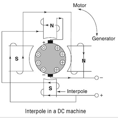
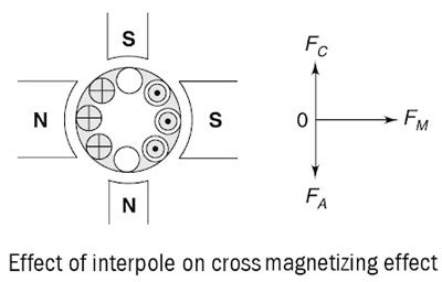
Thus, we can conclude that: The mmf induced on the interpoles must be sufficient enough to neutralize the effect of armature reaction and to produce enough field in the interpole winding to overcome the reactance voltage due to commutation. Another important function of the interpole is to neutralize the cross-magnetizing effect of the armature reaction, as shown in Fig. Here, vector FM represents the MMF due to main poles, FA represents the cross-magnetizing mmf due to the armature reaction and FC represents the interpole mmf which is directly opposite to the FA so that they cancel each other out. It is important to note here that the interpoles do not affect the flux distribution under the pole faces. So, even by using the interpoles in the machine, the flux weakening problem is not completely eliminated. Most medium-sized general-purpose motors correct the sparking problems with the interpoles and just live with the flux weakening problems. Main Functions of the InterpoleInterpoles In DC Machine
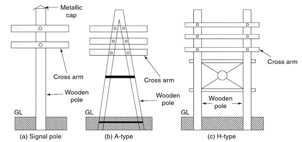
Ques.63. For what voltage is the H-type of poles used?
- 11 kV
- 22 kV
- 130 kV✓
- Any of the above
LINE SUPPORTS The main function of the line support is to support the conductors to keep them at suitable heights from the ground. Hence, in overhead lines, various types of supporting structures are used such as poles and towers which are called as line supports. Generally, line supports have the following properties: (i) Good mechanical strength (ii) Lightweight (iii) Cheap (iv) Longer life Various types of line supports are used in overhead transmission and distribution systems. The selection of line support depends on many factors such as cost, the span of the line, line voltage, local conditions, etc. The various types of line supports are as follows: This is one of the simplest forms of the line support. Generally, wooden poles are used. They are cheap, easily available and have good insulating properties. These poles must be straight, strong, and free from knots. The poles should be properly seasoned to prevent rapid decay because of crakes. An aluminum, zinc, or cement cap is used at the top of the wooden pole to prevent decay due to snow and rain. They are widely used for distribution purposes up to 22 kV and short spans (up to 60 metros). In cities where timber is easily available and the cost of transportation of steel tower is more, single and double pole structures either A or H type are widely used for overhead lines for 130 kV and for the span of 150 meters as shown in Fig. Wooden poles generally rot below the ground level and to prevent this preservative compounds such as creosote oil is used. Advantages of Wooden Poles Disadvantages of Wooden PolesWooden Poles:
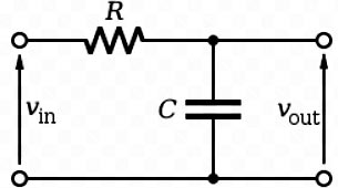
Ques.64. If an input signal with a non-zero direct current (dc) component is applied to a low pass RC network, then the D.C component in the output signal will be
- More than the input
- Same as the input
- Less than the input✓
- Zero
In electrical engineering, a filter is a frequency-selective circuit that passes a specified band of frequencies and blocks or attenuates signals of frequencies outside this band. These signals are usually voltages.
Passive Filter:- Filters that employ only passive elements such as capacitors, inductors, and resistors are called passive filters. In low-frequency applications (up to 100kHz), passive filters are generally constructed using simple RC (Resistor-Capacitor) networks, while higher frequency filters (above 100kHz) are usually made from RLC(Resistor-Inductor-Capacitor) components.
Active Filter:- When we apply a voltage across them or pass a current through them, they react in a certain orderly way according to simple rules, such as Ohm’s Law. They do not amplify the input signal, therefore, their output level is always less than the input.
Filters that make use of the properties of op-amps in addition to resistors and capacitors are called active filters such as Amplifier, transistors. Active components, such as transistors and op-amps, behave in a more complicated way and can have an amplifying effect on the current passed through them and the voltage applied across them.
Both active and passive filters are used in electronic circuits. However, active filters offer the following advantages over passive filters:
- The flexibility of gain and frequency adjustment: Since op-amps can provide a voltage gain, the input signal in active filters is not attenuated as it is in passive filters. It is easy to adjust or tune active filters.
- No loading effect: Because of the high input resistance and low output resistance of op-amps, active filters do not cause loading of the input source or the load.
- Cost and size: Active filters are less expensive than passive filters because of the availability of low-cost op-amps and the absence of inductors.
- Parasitics: Parasitics are reduced in active filters because of their smaller size.
- Digital integration: Analog filters and digital circuitry can be implemented on the same IC chip.
- Filtering functions: Active filters can realize a wider range of filtering functions than passive filters.
- Gain: An active filter can provide gain, whereas a passive filter often exhibits a significant loss.
Ques.65. Which of the following options is an Active transducer?
- Photovoltaic cell✓
- Photo-emissive cell
- Selsyn
- All of the above
The active transducers directly convert incident light into electricity using the photovoltaic effect. A photovoltaic transducer converts light energy directly into electrical energy light energy applied to this device causes the voltage to appear across its terminals. An increase in the intensity of light causes a corresponding increase in voltage. These transducers have been used for a number of years to energize satellites and spacecraft. Light from the sun, or solar energy, is converted directly into electrical power because of these applications, the photovoltaic cell is often described as a solar cell or solar battery. Photovoltaic cells are classified as active transducers because of their voltage-generating properties.
Ques.66. The value of the capacitor in a capacitor start motor controls the
- Speed of motor
- Starting torque✓
- Efficiency
- None of these
Capacitor-Start Motors The capacitor starts motor is identical to the split-phase motor in both construction and operation, except that a capacitor is installed in series with the starting winding, as shown in Fig. Also, the starting winding of the capacitor start motor is usually wound with a larger wire than that used for the starting winding of the split-phase motor. The use of a capacitor in series with the starting winding causes the current in this winding to lead the voltage, whereas the current in the running winding lags the voltage by virtue of the high inductance of that winding. With this arrangement. the phase displacement between the two windings can be made to approach 90 electrical degrees so that our two-phase starting is achieved. For this reason, the starting torque of the capacitor start motor is very high, which makes it an ideal drive for the small compressor that must be started under full load. So if the low value of the capacitor is used in the motor the phase angle between the starting and running winding will be reduced and the motor can’t generate enough torque to rotate the motor.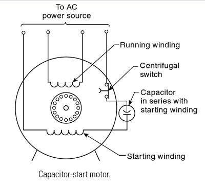
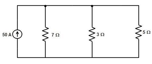
Ques.67. Determine the current flowing through the 7-Ω and 3Ω and 5Ωresistors, respectively in the following circuit
- 5A, 4.8 A, 12 A
- 10.56 A, 24.64A and 14.79A✓
- 11.254 A, 9.582 A, 7.36A
- 2A, 4A , 4.56A
By applying the current division rule in the given circuit to find the current in the 7-Ω resistance I1 = I × (R2R3) ⁄ (R1R2 + R2R3 + R3R1) I1 = (50 × 3 × 5) ⁄ (7 × 3 + 3 × 5 + 5 × 7) I1 = 750 ⁄ 71 = 10.56 A current in the 3-Ω resistance I2 = I × (R1R3) ⁄ (R1R2 + R2R3 + R3R1) I2 = (50 × 7 × 5) ⁄ (7 × 3 + 3 × 5 + 5 × 7) I2 = 1750 ⁄ 71 = 24. 64A current in the 5-Ω resistance I3 = I × (R1R2) ⁄ (R1R2 + R2R3 + R3R1) I3 = (50 × 7 × 3) ⁄ (7 × 3 + 3 × 5 + 5 × 7) I3 = 1050 ⁄ 71 = 14.79 A
Ques.68. Unit of magnetic flux is
- Weber/m2
- Coulomb
- Ampere
- Weber✓
S.I. unit of magnetic flux is weber abbreviated as Wb and C.G.S. unit of magnetic flux is maxwell abbreviated as Mx. These are defined as follows: When the magnetic field of one Tesla passes normally through 1 m2 area of a surface then magnetic flux linked with this surface is defined as 1 Weber.
Ques.69. A potential divider is normally connected
- At a distance V/100 meters from the generator where V is the voltage to be measured KV
- Outside the generator circuit towards the load circuit✓
- Within the generator circuit
- None of these
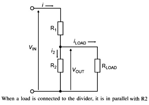
A potential divider is a resistor network that produces a fixed or variable potential (voltage). This potential is lower than the potential of the supply. A voltage divider (or potential divider) is a series circuit that is used to provide two or more reduced voltages from a single input voltage source. Essentially, a potential divider consists of two resistors connected in series. Assuming that no current flows out of the divider at the junction of R1 and R2, the same current, I, flows through both resistors. Ohm’s law applies to each resistor. For R2: i = Vout/R2 Ohm’s Law also applies to the two resistors when connected in series: i = VlN/(R1 + R2) Combining these two equations: VOUT/R2 = VlN/(R1 + R2) VOUT = VIN × R2/(R1 + R2) This equation states that the output voltage is directly proportional to the input voltage and the ratio of R1 and R2. Effect of Load The foregoing calculation assumes that no current flows out of the output terminal. However, the current is drawn from the output in most practical circuits. This is what happens: Current I passes through R1. At the output of the divider, a current ILOAD passes through the load while the remainder I2 passes on through R2. The diagram shows that R2 and the load (RLOAD) are resistances in parallel. If R2 and the load are resistances in parallel, their combined resistance is less than the resistance of either of them separately. Therefore the PD across R2 is less when the load is connected. The measured value of Vout is less than expected. Loading a voltage divider has the following effects: (i) The output voltage is reduced depending upon the value of load resistance RL. (ii) The current drawn from the source is increased because the total resistance of the circuit is reduced. The decrease in total resistance is due to the fact that the loaded voltage divider becomes the series-parallel circuit. (iii) The voltage divider should always be connected outside the generator circuit towards the load circuit (Test object) for accurate measurement.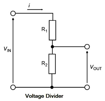
Ques.70. Internal heating of the capacitor is usually attributed to
- Leakage resistance✓
- Dielectric charge
- Plate vibration
- Electron Movement
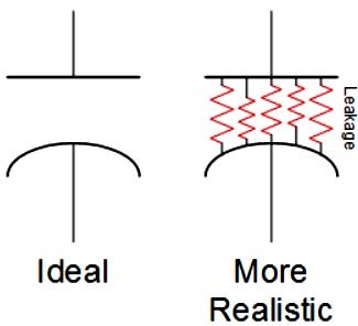
Leakage Resistance of a Capacitor Consider a capacitor charged by a de voltage source. After the charging voltage is removed, a perfect capacitor would hold its charge indefinitely Because there is no such thing as a perfect insulator, however, the charge stored in the capacitor will eventually leak or bleed off, thus neutralizing the capacitor. There are three leakage paths through which the capacitor might discharge: For paper, film, mica, and ceramic, the leakage current is very slight, or inversely, the leakage resistance is very high. The leakage resistance is much less for larger capacitors, such as electrolytic Capacitors. In general, the larger the capacitance of a capacitor, the lower its leakage resistance. Note that the leakage current in capacitors is fairly temperature-sensitive. The higher the temperature, the greater the leakage current (because of lower leakage resistance). The I2R loss is produced due to that leakage resistance. Hence, the internal loss happens due to the leakage power loss inside the capacitor. The temperature at which the dielectric operates is a function of the ambient temperature in which the capacitor is located; the heat which is radiated or conducted to the capacitor; the internal heating of the capacitor due to power losses in the conductors and dielectric; the physical construction and thermal conductivity of the materials inside the capacitors; the transfer of heat internally by conduction and convection to the container; and the heat lost from the container by convection, conduction, and radiation.