
Ques.131. Commutator motor has
- Uniform torque
- Approximately uniform torque
- Non-uniform torque✓
- None of these
All dc machines are equipped with commutators. However, the commutator is also used in some ac machines, i.e. ac motors in the fractional horsepower range as well as larger rated ac motors. For diverse requirements of industrial drives, the plain induction motor is not suitable being essentially a constant-speed motor with low power factor. Therefore in the case of industrial drives requiring variable speed and good power factor, the use of ac commutator motors assumes considerable importance. Finally, larger rated ac commutator motors have also been developed based on the principle of operation of Schrage motor. AC commutator motors, like comparable DC motors, have higher starting torque and higher speed than AC induction motors. The series motor operates well above the synchronous speed of a conventional AC motor. AC commutator motors may be either single-phase or poly-phase. In commutator motor (universal Motor) during the positive half cycle, the flux and the armature current are in positive direction thus torque is in the positive direction. During the negative half cycle, both the flux and the armature current reverse but its product is positive. So, torque remains positive. The torque developed is not of constant magnitude, but pulsates between zero and maximum value each half-cycles. The power in a single-phase system pulsates at twice the line frequency. However, the sum of the power in the three phases in a three-phase system remains constant. Therefore, a three-phase motor develops a uniform torque, whereas a single-phase motor develops pulsating torque.
Ques.132. Which of the following parts in a DC motor can bear maximum temperature conditions?
- Field winding
- Commutator✓
- Armature Winding
- Field magnets
Ques.133. Which of the following phenomenon shows the regulation of an alternator?
- The increase in terminal voltage when the load is thrown off✓
- The variation of terminal voltage under the condition of over and under excitation
- Terminal voltage at zero power factor
- The reduction in terminal voltage when the alternator is on the full load
Voltage regulation is defined in terms of the drop in potential difference at the alternator terminals when the load is applied. This drop is expressed as a percentage of the full-load potential difference when the speed and the dc field current are held constant. Voltage regulation of an alternator is defined as the increase in terminal voltage when the full load is thrown off (removed) keeping excitation and speed constant. Full load regulation = Rise in terminal voltage when the full load is thrown off ⁄ Normal full load terminal voltage Full load regulation = (Eo − Vo) ⁄ Vo Eo = Terminal voltage at no load Vo = Terminal voltage at full load
Ques.134. Which one is increased when the negative feedback voltage is applied to an amplifier?
- Input Impedance✓
- Output Impedance
- Voltage Gain
- Impedance Matching
Feedback is commonly used in amplifier circuits. A signal that is proportional to the output is compared with input or a reference signal so that the desired output is obtained from the amplifier. The difference between the input and the feedback signals, called the error signal, is amplified by the amplifier. There are two types of feedback: In negative feedback, the signal that is fed back to the input side is known as the feedback signal, and its polarity is opposite that of the input signal (i.e., it is out of phase by 180° with respect to the input signal). So the input voltage applied to the basic amplifier is decreased and correspondingly the output is decreased. Hence, the voltage gain is reduced. This type of feedback is known as negative or degenerative feedback. Negative feedback in an amplifier has four major benefits: (i) It stabilizes the overall gain of the amplifier with respect to parameter variations due to temperature, supply voltage, and so on (ii) Noise Reduction: Negative feedback when used in amplifiers increases the signal to the noise ratio or causes the reduction in noise. (iii) Increase in Input Impedance: Negative feedback increases the input impedance of the amplifier which is generally preferred in multistage amplifiers to reduce the loading effect. The negative voltage feedback increases the input impedance and decreases the output impedance of the amplifier Such a change is probably in practice as the amplifier can then serve the purpose of impedance matching. If Zin is the input impedance of an amplifier without negative feedback, then it can be proved that with negative voltage feedback, the input impedance Z” if of the amplifier is given by, Z”if = Zin(1 + Aβ) Where A is the open-loop gain i.e gain without feedback β is the feedback factor Z“if = Input impedance after feedback Zin = Input impedance without feedback It is clear that by applying negative voltage feedback, the input impedance of the amplifier is increased by a factor (1 + Aβ) is much greater than unity, therefore, the input impedance is increased considerably. This is an advantage since the amplifier will now present less of a load to its source circuit. (iv) Non-linear Distortion: Reduction Application of negative feedback to amplifiers causes the amplifier characteristics to be least non-linear or more linearized and the distortion gets reduced by a factor of 1/(1 + Aβ). it increases the bandwidth.
Ques.135. The transition temperature of the mercury is
- 9.22°K
- 18.0°K
- 1.14°K
- 4.12°K✓
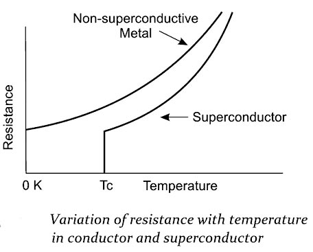
Superconductivity is a phenomenon in which certain metals, alloys, and ceramics conduct electricity without resistance when it is cooled below a certain temperature called the critical temperature. A superconductor is a material that loses all its resistance (offers zero resistance) to the flow of electric current when it is cooled below a certain temperature called the critical temperature or transition temperature TC. Examples: Mercury (Hg), Zinc (Zn), Vanadium (V), Tin (Sn) and Niobium (Nb). Properties of Superconductors Few important properties of superconductors are explained in brief in this section. (i) Critical temperature TC (Transition Temperature) The electrical resistance of the superconducting materials becomes zero below the transition temperature (Tc). This property is called the defining property of superconductors. The figure shows the variation of electrical resistance with respect to the temperature for the normal conductor and a superconductor. From the figure, it is noted that the resistance falls to zero at the transition temperature. Note:- Good electrical conductors such as silver (Ag), Gold (Au) and copper (Cu) are not good superconductors because the resistivity of these conductors at low temperatures is limited to the low resistivity. Similarly, good superconducting materials like Zn and Pb are not good electrical conductors. The temperature at which mercury becomes superconducting was found to be close to the boiling point of liquid helium (4 2 K).
Ques.136. The region along load line including all points between saturation and the cut-off is known as:-
- Saturation region
- Linear region✓
- Cut-off region
- None of these
The output characteristics can be divided into four distinct regions. namely, the active region, the saturation region, the Linear region, and the cut-off region. In the active region, the collector junction is reverse biased and the emitter junction is forward biased. In the output characteristics, the active region is the area to the right of the ordinate VCE= a few tenths of a volt and above IB = 0. In this region, the transistor output current responds most sensitively to an input signal. If the transistor is to be used as an amplifying device without appreciable distortion, it must be restricted to operate in this region. In the active region, IC is practically independent of VCE and is determined only by lE. The active region lies between cutoff and saturation points. The region of the output characteristics where both junctions (emitter and collector) are forward biased, is known as the saturation region of the transistor. The saturation region is located to the left of the ordinate. VCB is slightly positive for a p-n-p transistor in this region. This forward biasing of the collector-base junction causes the collector current to change exponentially with the collector-base forward voltage, as in p-n diode. The large change in the collector current for a small change in VCB in the saturation region is thus accounted. A forward bias implies that the collector p material is at a positive potential relative to the base n material. A hole current thus flows from the collector to the base, i.e., in a direction opposite to the original hole current due to the transistor action. When the forward bias is sufficiently large, the hole flow from the collector to the base predominates, forcing Ic to be positive, as shown in Fig. The region of the output characteristics where both the junctions (emitter and collector) are reverse biased, is known as the cutoff region of the transistor. In order to cut off the transistor, it is not enough to reduce lB to zero. Instead, it is necessary to reverse bias the emitter junction slightly. The cut-off is thus defined as the condition where the collector current is equal to the reverse saturation current ICO and the emitter current is zero. Linear Region:- The region along the load line including all points between saturation and cutoff is generally known as the linear region of the transistor’s operation. As long as the transistor is operated in this region, the output voltage is ideally a linear reproduction Note:- Cutoff region: in this region transistor acts as off switch. Saturation region: transistor acts as on switch. Active region: transistor acts as an amplifier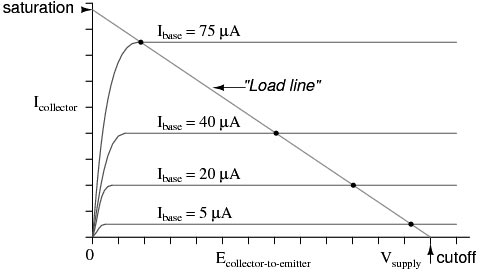
Active Region
Saturation Region
Cut-off Region
Ques.137. Gain in kinetic energy is equal to:-
- Loss in P.E + Work against friction
- Loss in P.E × Work against friction
- Loss in P.E − Work against friction✓
- Loss in K.E − Work against friction
Kinetic Energy is the energy possessed by an object because of its motion. Now consider this from the point of view of a falling body. Let a body of mass be at rest at a height of h. Its weight is mg and it contains potential energy equal to mgh but no kinetic energy because it is not moving. If the mass is allowed to fall, it gains kinetic energy as it increases velocity, the gain in kinetic energy being equal to the loss of potential energy. Just before the body reaches the ground, it has fallen through h, lost all its potential energy, and gained an equal amount of kinetic energy. kinetic energy gained= potential energy lost − Work against friction
Ques.138. Harmonics in any transformer are generated due to which of the following factor?
- Varying current in the winding
- varying load
- Saturation of core✓
- Poor insulating properties
Harmonics cause distortions of voltage and current waveforms, which have adverse effects on electrical equipment. Harmonics are one of the major power quality concerns. In the linear portion of the curve, as the current increases, the magnetic flux density increases. However, a point is reached where further increases in current yield smaller and smaller increases in flux density. This point is called the saturation point and is characterized by a dramatic reduction in the slope of the curve. In fact, the curve is no longer linear. Because the slope of the flux-current curve is proportional to the inductance of the coil, the reduction in the slope causes reduction in the inductance. The new inductance may be 100 times less than the inductance in the linear portion of the curve. As shown on the hysteresis curve in, the magnitude of the current that causes the iron to go into saturation is not the same as the magnitude at which the iron comes out of saturation. The boundary between linear operation and saturated operation is not fixed but, instead, depends on the previous values of that current. The hysteresis phenomenon is a fundamental property of ferromagnetic materials. Hysteresis occurs because of residual flux density stored in the iron that must be overcome when the current changes direction. It should be noted that, for a particular value of flux, there are two values of current for which the core would be in saturation. The presence of harmonics causes overheating, power loss, reduced efficiency and shortened lifespan of the devices.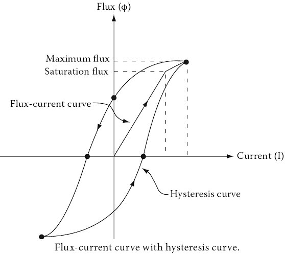
Ques.139. Current passing through resistor R2:-
- 1.65 mA✓
- 1 mA
- 1.75 mA
- 1.25 mA
Ques.140. The flux of the magnetic circuit is analogous to which of the following terms in an electric circuit?
- Conductivity
- Current density
- Current✓
- E.M.F
All the laws applicable to electric circuits such as Ohm’s law, Kirchhoff’s, laws, etc. can be applied to magnetic circuits simply by replacing the electrical terms with the corresponding magnetic terms. Flux in a magnetic circuit is analogous to the current flowing in an electrical circuit. Magnetomotive force for the magnetic circuit is analogous to electromotive force for the electrical circuit. In the magnetic circuit, after applying MMF to the circuit we shall get a magnetic flux flow (φ) in the circuit. Similarly, we shall get electric current flow (I) caused by emf (e) in the circuit. With a similar analogy, different electrical terms can be replaced by similar magnetic terms Ohm’s law for electrical circuits is, EMF = Current × Resistance with the above analogy, Ohm’s law for the magnetic circuit will be, MMF = flux × reluctance

