Ques.61. State an example of plastic welding?
- Gas Welding
- Resistance welding✓
- Thermit welding without pressure
- None of these
There are two main types of the welding process. They are (a) Plastic weldings (b) Fusion welding, In plastic welding & the metal, pieces are heated to a plastic state. They are praised together to make the joint. Plastic welding is also known as pressure welding. Electric resistance welding such as spot welding is an example of plastic welding. In fusion welding, the metal at the joint is heated to the molten state. Then it is allowed to solidify. Pressure is not applied in this welding process. So it is known as non-pressure welds. Gas welding and electric arc welding are examples of fusion welding.
Ques.62. Household energy meter falls under the category of which type of instrument?
- A magnetically revolving type instrument
- A recording instrument
- A displaying instrument
- An integrating instrument✓
Integrating instruments are those which measure the total amount of the electrical quantity (e.g. energy) supplied over a period of time.
In such instruments, there are sets of dials or gears which register the total quantity of electricity or the total amount of electrical energy supplied to a circuit in a given period. The Household energy meter is an integrating instrument. Ampere-hour meter another example of integrating instruments.
Ques.63. Among these which one is correct about the characteristics of the transistor?
- It has very low input impedance
- It has zero input impedance
- It has the high input impedance✓
- It has low input impedance
The input and output impedance of transistors depends on quite a lot on the technology of the transistor and on the way it is used in a circuit. A bipolar transistor used as a common collector amplifier will have a high input impedance and a low output impedance. The same transistor used as a common base amplifier will have a low input impedance and a high output impedance. We typically don’t like low input impedance because we would like to control things using very little current. A low input impedance draws current. Also, we typically like low output impedance when the transistor is on and a high output resistance when it is off. Advantages of bipolar junction transistor (BJT) are as given below, There are some disadvantages of bipolar junction transistor (BJT) are as given below,
Ques.64. The dielectric constant of air is___
- Less than 1
- Equal to 1✓
- Can’t be determined
- Zero
Ques.65. Magnetic bubbles are used as___
- Routing telephones call
- Thermostat
- Storage device✓
- Strain gauge
Bubble memory is a type of non-volatile computer memory. If the surface of a non-magnetic material is coated with a thin layer of magnetic material which magnetized in a small magnetized in the opposite direction away from the surface. These bubbles can be moved around and used to represent the binary digits. They can be magnetized only in one direction. Bubble memories can not replace the main memory (CMOS) because they are too slow. However, they can contain a great deal of information in a small space and may be used to replace the magnetic disc eventually, as they have the advantage of no moving parts. Bubble memory is highly reliable, it is not susceptible to environmental fluctuations and it can operate on battery power for a considerable period of time. These qualities make bubble memory well suited for use with industrial robots and in portable computers.
Ques.66. If the instrument have a wide range, then instrument should have_______
- Square law scale
- Linear scale
- Exponential scale
- Logarithmic scale✓
Various Scales for measurement through an instrument are 1. Linear Scales:- A linear scale like a foot rule, is the simplest to read. Though termed as linear it may form a part of the arc, however, the graduations will be uniformly disturbed. The moving coil electrodynamic wattmeters generally have the linear scale. Moving iron instruments also have nearly linear scales. 2. Square low scale:- Some instruments like thermal instruments, electrodynamic voltmeters, and ammeters follow the square law scale. 3. Logarithmic scale:- The logarithm and its use is nothing more than a mathematical tool which simplifies dealing with very large and very small numbers. For example, the logarithm of the number 1,000,000 is six, and the logarithm of the number 0.000001 is -six (minus six). Obviously, as more zeros are added before or after the decimal point, convening these numbers to their logarithms greatly simplifies calculations which use these number. If the current to be measured extends over a wide dynamic range, for example spanning several orders of magnitude, there is a risk that the signal conditioning circuit can saturate at its upper or lower limit and no measurement will be obtained. This problem can arise in the measurement of photocurrents in the atmosphere which span a large range of values during the daytime, and in atmospheric electricity measurements where currents generated in elevated points vary between HA in disturbed weather to pA in fair weather. An alternative approach for current measurement is therefore needed if, in preserving the capability to measure large currents, good resolution is still required at the low current end of the range. A wide operating range can be achieved with a logarithmic current amplifier, which generates an output voltage proportional to the logarithm of the input current. This can be implemented with an opamp by using a device having an exponential voltage-current response in place of the feedback resistor of the trans-resistance configuration, such as a diode. Similarly, we use logarithmic scales for things that come in an extremely wide variety of sizes. Earthquakes are just one example: a 9.0 earthquake releases a trillion times as much energy as a 1.0 earthquake. If we used a linear scale, we would have to use giant numbers to describe earthquakes; for example, a 6.0 magnitude earthquake would be a 1,000,000,000 size earthquake, and a 9.0 magnitude earthquake would be described as a 1,000,000,000,000 size earthquake.
Ques.67. How many types of dependent source are there?
- 1
- 4✓
- 2
- 3
Classifying the types of dependent sources There are four types of dependent sources exist Voltage-controlled voltage source (VCVS): A voltage across the input terminals controls a dependent voltage source at the output port. Current-controlled voltage source (CCVS): A current flowing through the input terminals controls a dependent voltage source. Voltage controlled current source (VCCS): Now account for a dependent current source at the output terminals. With a voltage across the input, you can control the amount of current output. Current-controlled current source (CCCS): With a current flowing through the input port, you can control a dependent current source at the output port.
Ques.68. How much eddy current loss does an air-core inductor have?
- Very less✓
- Constant
- Zero
- High
An inductor or a coil may be defined as an electrical component that is manufactured with a specific amount of inductance which is the property of a coil that opposes changes in current by means of energy storage in the form of the magnetic field. When a current flows through a coiled wire, an electromotive force is generated in such a way that it opposes the flow of current. The inductors are used in tunning, filter circuits, transformers, and coupled circuits to transfer or couple energy from one ckt to another. The inductor is also known as the choke. Based on the type of core used, inductors can be classified as Iron core inductor: The iron core inductor is made of copper wire-wound on a laminated iron core. The laminated core is used to avoid eddy current losses. The laminated core consists of thin iron sheets pressed together and insulated from each other. They are very stable for audio frequency applications. Air core inductor: The air core inductor is made of thin copper wire-wound over a former made of thick cardboard. It has a low value of inductance. Air cores are the best for high-frequency applications, but they become excessively large as inductance and current increases. Essentially, air has an excellent frequency response but a poor ability to store magnetic energy. These are suitable for radiofrequency applications. Ferrite-core inductors: Ferrite core inductors are made of coils wire wound on a ferrite core. The ferrite-core has a very low edyy current loss. Ferrite has a reasonably high-frequency response (not as high as air) but it also has a significantly better ability to store energy. The typical applications of ferrite core inductors are in (i) r.f. chokes for supply decoupling purposes, (ii) switching regulated type d.c. power supplies, and (iii) various types of filters used in communication equipment. Variable inductors: Variable inductors are similar to the fixed ferrite-core inductor, however, the core is adjustable. These inductors are widely used in tuning circuits and in filter circuits.
Ques.69. How can we find the application of differentially compound D.C motors?
- Zero torque
- Armature resistance
- Constant speed✓
- Low starting torque
In the differential compound, motor two field windings i.e shunt and series windings oppose each other. In the differential compound motor, an increase in load creates an increase in current and a decrease in total flux in this type of motor. For the equation of DC motor Eb = V − IaRa So of if the current increase the back Emf decrease Now, torque is given by T=kØIa Hence if we increase the flux the armature current will decrease If we assume that load torque remains constant then according to the torque equation if field flux increases then lesser current will flow through the motor armature to produce the same torque which will increase the back emf in the armature due to the reduced resistive voltage drop across the armature due to reduced armature current. Now back emf is directly proportional to the product of field flux and rotor speed. Since from the given conditions both the back emf and field, flux has increased hence the motor speed will remain fairly constant. However, since an increase in load tends to decrease the field strength, the speed characteristic becomes unstable. Rarely is this type of motor used in aircraft systems.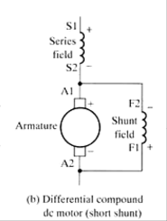
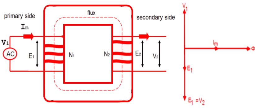
Ques.70. A property of a transformer that makes it ideal is:-
- CRGO core for its primary and secondary windings
- No losses and magnetic leakage✓
- Interleaved primary and the secondary winding
- None of these
Characteristics of an Ideal Transformer The ideal transformer posses the following characteristics:- Zero Leakage Flux No Core Losses Zero Winding Resistance Maximum Efficiency