Ques.91. To minimize loss due to hysteresis, the magnetic material should have?
High resistivity
High retentivity
Low hysteresis coefficient✓
Large B-H loop area
Hysteresis Loss
When a magnetic material is subjected to one cycle of magnetization, B always lags behind H so that the resultant B-H curve forms a closed loop, called hysteresis loop.
Hysteresis loss is present in all those electrical machines whose iron parts are subjected to cycles of magnetization. The obvious effect of hysteresis loss is the rise in temperature of the machine. It can be shown that hysteresis energy loss per cycle is directly proportional to the area of the hysteresis loop.
Steinmetz Hysteresis Law
To eliminate the need for finding the area of the hysteresis loop for computing the hysteresis loss, Steinmetz devised an empirical law for finding the hysteresis loss. He found that the area of the hysteresis loop of a magnetic material is directly proportional to 1.6 the power of the maximum flux density established.
Hysteresis Loss = Kh × BM1.67 × f × v watts
where Kh is the Hysteresis coefficient depends upon the material. The smaller the value of Kh of a magnetic material, the lesser is the hysteresis loss.
The armatures of electrical machines and transformer cores are made of magnetic materials having low hysteresis coefficient in order to reduce the hysteresis loss. The best transformer steels have Kh values around 130, for cast steel they are around 2500 and for cast iron about 3750.
Bm = Maximum flux density f = frequency v = Volume of the core
Ques.92. A conductor of length L has current I passing through it, when it is placed parallel to a magnetic field. The force experienced by the conductor will be?
BLI
B2LI
Zero✓
None of the above
FORCE ON CURRENT-CARRYING CONDUCTOR PLACED IN UNIFORM MAGNETIC FIELD
We know that a moving charge in a magnetic field experiences a force. Now electric current in a conductor is due to the drifting of free electrons in a definite direction in the conductor. When such a current-carrying conductor is placed in the uniform magnetic field, each free electron experience a force. Since the free electrons are constrained ii the conductor, the conductor itself experiences a force. Hence, a current-carrying conductor placed in a magnetic field experiences a force.
Expression for the force.
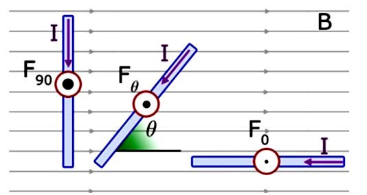
Consider a conductor of length I and area of cross-section A placed at an angle θ to the direction of a uniform magnetic field Β as shown in the figure
F = B.I.L.sinθ
Special case:-
When θ = 0° or 180° i.e sinθ = 0
F = 0 (Minimum value)
Thus if a current-carrying conductor is placed parallel to the direction of the magnetic field, the conductor will experience no force.
When θ = 90° sinθ = 1
F = 1 (maximum value)
Hence, a current-carrying conductor will experience a maximum force when it is placed at right angles to the direction of the magnetic field.
Ques.93. Another name of unity gain amplifier is?
Voltage follower✓
Difference amplifier
Comparator
All of these
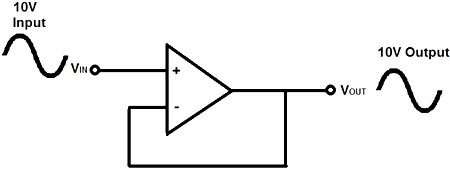
In Voltage follower configuration, the output of the op-amp follows the input in magnitude and phase, i.e. the output voltage follows the input voltage. So it is called the voltage follower. This circuit acts as a voltage source having negligible internal resistance. From the circuit,
Vout = Vin
This circuit has high input impedance and zero output impedance with unity gain. Due to this reason, a voltage follower circuit is used as a buffer for impedance matching. It is also called source follower, unity gain amplifier, buffer amplifier or isolation amplifier.
Ques.94. If the field current of a three-phase alternator is reversed, what happens to its phase sequence?
Remain same✓
Reverses
Two phases are exchanged
It becomes AC motor
The direction of rotation of the synchronous motor is determined by its starting direction, as initiated by induction motor action.
Thus, to reverse the direction of a 3 phase synchronous motor, it is necessary to first stop the motor and then reverse the phase sequence of the 3 phase connections at the stator. Reversing the field current of the alternator will not affect the direction of the synchronous motor as field current is independent of the phase sequence.
Ques.95. FInd the current flowing through the resistance R3?
1.95 mA
2.5 mA
2 mA
1.55 mA
Ques.96. Find the current flowing through resistor R2?
5A
2A
1.51 A
1.25 A
Ques.97. Find the current flowing through resistor R1?
440 microA
445 mA
442 mA
442 microA
Ques.98. Find the symmetrical breaking current of a three-phase circuit, 33 kV oil circuit breaker is rated 1200 A, 2000 MVA, 3s.
35 kA✓
3600 A
104.8 kA
1400 A
Breaking capacity of Circuit Breaker
When the breaker is closed and a fault occurs then it closes in the transient state(in transient state DC offset become zero) so the current capacity at this instant is only the RMS value of current(symmetrical component)in the transient state which is also called breaking capacity of the breaker.i.e
Breaking capacity = RMS value of breaking current in the transient state.
The breaking capacity of the three-phase circuit breaker is generally expressed in MVA and it is given as
Breaking capacity = √3 × rated voltage in kV × Rated current in kA