Ques 41. Select the correct definition of power gain ratio.
Output power to Input power✓
Output voltage to Input voltage
Input Voltage to output power
Input power to output power
The power gain of an electrical network is the ratio of an output power to an input power.
Power gain determines how much the output power is larger than the input power. Because power is the product of voltage and current, power gain is determined from the multiplication of current gain and voltage gain.
Ques.42. Select the correct statement regarding a semiconductor.
Acceptor level lies close to the valence band✓
N-type semiconductor behave as a conductor at 0°K
Donor level lies close to the valence band
All of these
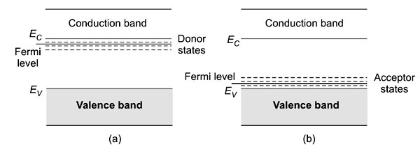
Semiconductors can be classified into two types—intrinsic and extrinsic. Intrinsic semiconductors are pure elements like Si and Ge. At 0 K, the valence band is completely filled and the conduction band is empty. Semiconductors obtained by adding impurities (known as doping) to pure semiconductors are called extrinsic semiconductors. Depending on the type of impurity used, semiconductors can be classified into n-type and p-type.
If a group V (pentavalent) element like arsenic or phosphorous is added to the group IV element, four electrons of the group V element combine with those of the group IV element to form covalent bonds. The remaining one electron of the impurity atom is very weakly bonded with the parent atom and can easily be excited to the conduction band. This material in which, the conduction is due to these free electrons (called majority charge carriers) is called an n-type semiconductor. The impurity atom which donates free electrons to the crystal is called the donor.
The donor energy levels lie below the conduction band edge [Fig.(a)]. If the doping is by group III element, all the three valence electrons enter into covalent bonding, leaving the vacancy of an electron to form saturated bonds. Thus, doping creates a hole. The material is called a p-type semiconductor with holes as the majority charge carriers. The impurity is called an acceptor impurity.
Acceptor levels lie just above the valence band edge [Fig. 12.8(b)]. The Fermi level shifts upwards and lies close to the conduction band in n-type semiconductors. In p-type semiconductors, the Fermi level is closer to the valence band edge. These are also shown in Fig. 12.8.
Valance band (VB) is usually completely filled with electrons at absolute zero. In contrast, the conduction band (CB) contains full unoccupied states at absolute zero.
As the name suggests it is the acceptor band ie it will accept the electrons. Since the electrons present in the valence band. So, the acceptor band being closer to the valence band accepts electrons from it and creates holes.
Similarly, in n-type semiconductors, the donor band lies closer to the conduction band as it donates it’s electrons to the conduction band so that the flow of charge carriers can take place easily.
Ques.43. How will the magnetic lines of force bend away from their usual paths in order to pass through the piece?
When an iron piece is placed perpendicular to the magnetic field
When an iron piece is placed in a parallel plate capacitor
When an iron piece is placed in a magnetic field✓
When an iron piece is placed in an electric field
Magnetic Shields
Because all materials have some ability to conduct magnetic lines of force, it is not practical to make a magnetic insulator. Strong magnets placed near electrical instruments can cause permanent damage. Therefore, it is necessary to prevent the magnetic flux (lines of force) from passing through the instrument. Magnetic flux can be bent, distorted, and guided by low-reluctance materials inserted in the magnetic field.
The external field of a magnet is distorted when any magnetic substance is placed in that field because it is easier for the lines of force to travel through the magnetic substance than through the air. The opposition of a material to magnetic flux is called reluctance and compares to resistance in an electric circuit.
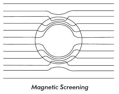
When a piece of soft iron is placed near a magnet, the field is distorted and the lines tend to pass through the iron instead of the air leaving the field weaker elsewhere. The effect of an iron ring or of a cylinder placed in a magnetic field is shown in Figure.
Iron is a better conductor of magnetism than air. This fact is utilized in constructing magnetic shields. Many expensive instruments that may be subjected to magnetic influences are surrounded by iron or iron alloys. The iron provides a magnetic path around the sensitive parts. There is little tendency for the flux lines to leave the iron and pass through an air medium and to return again to the same iron path.
Magnetic screening is of frequent application in telecommunication equipment to prevent undesirable magnetic interference between adjacent components.
Ques.44. When will the self-inductance of an inductive coil is doubled?
Both the number of turns and the core length of an inductor coil are equals
Both the number of turns and the core length of an inductive coil are doubled✓
Both the number of turns and the core length of an inductive coil are halved
The number of turns and the core length of an inductor coil are zero.
The self-inductance of the coil can also be written as
L = μN2A/I
where
N is the number of turns of the solenoid
A is the area of each turn of the coil
l is the length of the solenoid
and μ is the permeability constant
Let us assume that area and permeability is constant then new self-inductance will be
L1 = N2/I
So if the number of turns and length is doubled
L1 = 22/2
L1 = 2L
Therefore if we double the number of turns and the core length of an inductive coil are doubled
Ques.45. When the collector junction in a transistor is biased in the reverse direction and the emitter junction in the forward direction, the transistor is said to be is the:-
Saturation
Cutoff region
Active region✓
None of these
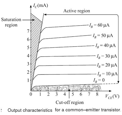
The output characteristics can be divided into three distinct regions. namely, the active region, the saturation region, and the cut-off region.
Active Region
In the active region, the collector junction is reverse biased and the emitter junction is forward biased. In the output characteristics, the active region is the area to the right of the ordinate VCE= a few tenths of a volt and above IB = 0. In this region, the transistor output current responds most sensitively to an input signal. If the transistor is to be used as an amplifying device without appreciable distortion, it must be restricted to operate in this region.
In the active region, IC is practically independent of VCE and is determined only by lE. The active region lies between cutoff and saturation points.
Saturation Region
The region of the output characteristics where both junctions (emitter and collector) are forward biased, is known as the saturation region of the transistor.
The saturation region is located to the left of the ordinate. VCB is slightly positive for a p-n-p transistor in this region. This forward biasing of the collector-base junction causes the collector current to change exponentially with the collector-base forward voltage, as in p-n diode. The large change in the collector current for a small change in VCB in the saturation region is thus accounted.
A forward bias implies that the collector p material is at a positive potential relative to the base n material. A hole current thus flows from the collector to the base, i.e., in a direction opposite to the original hole current due to the transistor action. When the forward-bias is sufficiently large, the hole flow from the collector to the base predominates, forcing Ic to be positive, as shown in Fig.
Cut-off Region
The region of the output characteristics where both the junctions (emitter and collector) are reverse biased, is known as the cutoff region of the transistor.
In order to cut-off the transistor, it is not enough to reduce lB to zero. Instead, it is necessary to reverse bias the emitter junction slightly. The cut-off is thus defined as the condition where the collector current is equal to the reverse saturation current ICO and the emitter current is zero.
Note:-
Cutoff region: in this region transistor acts as off switch.
Saturation region: transistor acts as on switch.
Active region: transistor acts as an amplifier
Ques.46. When an AC power is applied to a circuit having reactive load, then the voltage is _______
90 degree out of phase with current✓
180 degree out of phase with the current
In phase with the current
270 degree out of phase with the current
The AC power can be applied to resistor, capacitor and inductive circuit. The capacitor and inductive circuit are known as the reactive load.
In a purely resistive load, the current and voltage are in phase with each other i.e the phase displacement in the voltage and current is zero degree.
Whereas in the case of inductor or capacitor the voltage or current are out of phase. In the case of an inductor, the voltage leads the current by 90°, whereas in the capacitor the current lead voltage by 90°
Ques.47. Two long parallel conductors are placed 10mm apart from each other carrying the current of 150 amperes. What will be force per meter length of each one?
0.45 N
0.1 N
4.5 N✓
9 N
Force per meter in a parallel conductor is given as
F = (2 × 10⁻⁷ × I1 × I2) ⁄ d
I1 = I2 = 150 Ampere
Distance = 10mm = 0.01m
F = (2 × 10−7 × 150 × 150) ⁄ 0.01
F = 4.5 N
Ques.48. Binary vapor cycles are used to
Increase efficiency of the turbine
Increase the efficiency of the plant✓
Increase the performance of the conductor
Balance the efficiency of turbine
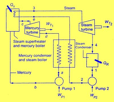
The binary vapor cycle is the combination of two cycles. One operates in the high-temperature region, while other operates in the low-temperature region.
It uses two working fluids one with good high-temperature characteristics and another with good operating characteristics at the lower temperature.
In the binary vapor cycle, the two ideal Ranking cycles are combined such that the condenser of the high-temperature cycle (also called topping cycle) serves as the boiler for the lower temperature cycle (bottoming cycle). Thus the heat rejection of the topping cycle is used as a heat input to the bottoming cycle.
Binary vapor cycle is generally used to increase the overall efficiency of the plant. Two fluids (mercury and water) are used in cascade in the binary cycle for production of power.
The few more property required for an ideal binary fluid used in high-temperature limit are listed below:
It should have a high critical temperature at reasonably low pressure.
It should have a high heat of vaporization to keep the weight of fluid in the Cycle to the minimum.
The freezing temperature should be below room temperature.
It should have chemical stability through the working cycle.
It must be non-corrosive to the metals normally used in power plants.
It must have the ability to wet the metal surfaces to promote heat transfer.
The vapor pressure at a desirable condensation temperature should be nearly atmospheric which will eliminate the requirement of power for the maintenance of vacuum in the condenser.
After expansion through the prime mover, the vapor should be nearby saturated so that a desirable heat transfer coefficient can be obtained which will reduce the size of the condenser required.
Ques.49. In a straight wire, induced current depends upon which of the following factors?
Magnitude of magnetic flux density
The speed of movement of wire
Number of turns
All of these✓
The production of electric current by moving a straight conductor in a magnetic field is called electromagnetic induction. The current produced in the conductor is called induced current.
Faraday’s experiment
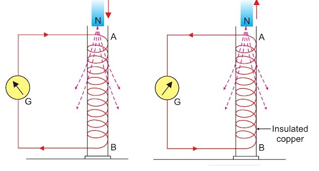
An insulated copper wire is wound over a cardboard tube and the ends of it are connected to a sensitive galvanometer. When the north pole of a powerful magnet is suddenly inserted in the coil, it is observed that galvanometer G shows a deflection for a moment and then its needle comes back to the central zero position. It is further noticed that when the north pole of the magnet is well within the coil, but not moving, there is no deflection shown by the needle of the galvanometer.
At this state, if the north pole of the magnet is suddenly pulled out, then the needle of galvanometer shows deflection for a moment in the opposite direction.
If we continue moving the magnet up and down within the coil, the magnetic needle continues showing deflection from left to right and vice versa. However, as soon as we stop the motion of magnet with respect to the coil, there is no deflection in the galvanometer.
Furthermore, it is observed that if we do the experiment by inserting south pole of the magnet, a current is induced in the coil, but the deflection of galvanometer needle is in the opposite direction.
It has also been observed that if we increase the strength of magnet or the number of turns in the coil, the magnitude of induced current increases.
Conclusions from Faraday’s Experiment
1. Whenever the magnet is moved with respect to coil, i.e., the strength of magnetic field changes within the coil, an induced current is produced in the coil.
2. The induced current is not produced in a coil if the motion of the magnet with respect to the coil stops, i.e., the strength of magnetic field stops changing within the coil.
3. The magnitude of induced current produced in the coil changes with the increase or decrease of the magnetic lines of force within the coil, i.e., changes with the change in magnetic intensity.
4. The induced current produced within the coil is alternating in nature i.e., changes its direction with the change in the magnetic lines of force passing through coil. Such current is commonly called AC which means alternating current.
5. The induced current produced is instantaneous in nature. It means it lasts for very short duration.
6. The magnitude of induced current depends upon
(i) the strength of inducing magnet:- The strength ol the induced current increases with the strength of the magnetic field (or power of the magnet).
(ii) the number of turns in the closed coil:- Larger the number of tums in the coil, stronger lo the induced current.
(iii) The relative speed between the coil and the magnet: Higher the relative speed between the coil and the magnet, stronger la the induced current.
Also from the Faraday’s law the induced EMF
EMF = NΔφ/Δt
Where
N = number of turns
φ = BA= magnetic flux
B = External magnetic field
A = Area
Ques.50. In a synchronous motor, the breakdown torque is
Inversely proportional to the square of the applied voltage
Inversely proportional to applied voltage
Directly proportional to the applied voltage✓
Directly proportional to the square of the applied voltage
Breakdown Torque. The breakdown torque of a motor it the maximum torque that it will develop with rated voltage applied at the rated frequency, without an abrupt drop in speed
Pull-Out Torque. The pull-out torque of a synchronous motor is the maximum sustained torque that the motor will develop at synchronous speed with rated voltage applied at a rated frequency and with normal excitation.
The pull-out torque of a synchronous motor is
TP = 9.55 EbV ⁄ XS.Ns
Where
Eb = Back EMF
V = Applied Voltage
XS = Synchronous Reactance
Ns = Synchronous speed.
Hence from the above equation, it is clear that the pullout torque of the synchronous motor is directly proportional to the applied voltage