
Ques.51. In a BJT the base current(IB) is about ______ of emitter current (IE)
- 25%
- 20%
- 5%✓
- 35%
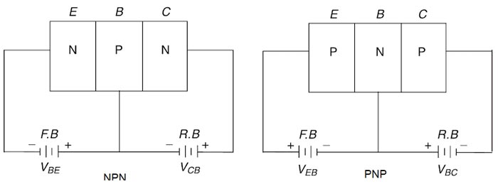
The bipolar junction transistor (BJT) is a semiconductor device with two PN junctions. Two different types of bipolar junction transistors exist, NPN- and PNP-type. This nomenclature describes the structure of the BJT, e.g. n-doped layer, p-doped layer, n-doped layer like for the NPN-type. One of the n-doped layers is heavily doped and called the emitter. The other n-doped layer is called the collector and the p-doped layer in between is the base. For the required functionality the base has to be very thin. Each of the three layers is connected to external terminals. Operation and Current Components of NPN Transistor The forward bias applied to the emitter-base junction of an NPN transistor causes a lot of electrons from the emitter region to crossover to the base region. As the base is lightly doped with the P-type impurity, the number of holes in the base region is very small and hence the number of electrons that combine with holes in the P-type base region is also very small. Hence a few electrons (almost 5%) combine with holes to constitute a base current IB. The remaining electrons (more than 95%) crossover into the collector region to constitute a collector current IC. Thus the base and collector current summed up gives the emitter current, i.e IE = – (IC + IB) In the external circuit of the NPN bipolar junction transistor, the magnitudes of the emitter current It the base current IB and the collector current IC are related by IE = IC + IB So the conclusion is: (a) For the normal operation of a BJT, the emitter diode is always forward biased and the collector diode reverses biased. (b) The collector current is almost equal to the emitter current. (c) The base current is always very small. Also from the above consideration, it is clear that IE = IC + IB Thus we find that in normal B1T operation a relatively large current is transferred from a low-to-high resistance circuit, that is, from forward-biased diode to a reverse-biased diode.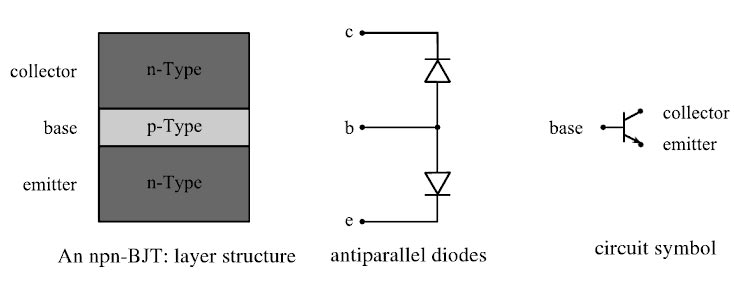
Ques.52. In a 3-phase dynamometer type power factor meter, two moving coil planes are inclined at an angle of
- 180°
- 120°✓
- 90°
- 45°
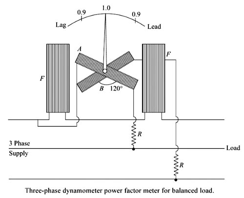
Power factor meters indicate the power factor of a circuit directly, as distinct from instruments from whose readings the power factor may be obtained by dividing the watts supplied, by the volt-amperes in the circuit. Power factor meters—like wattmeters—have a current circuit and a pressure circuit. The former carries the current in the circuit whose power factor is to be measured. The pressure circuit is usually split into two parallel paths – one inductive and one non-inductive-and the deflection of the instrument depends upon the phase differences between the main current and the currents in the two branches of the pressure circuit, i.e. upon the power factor of the circuit. Figure. shows the connections of a three-phase power factor meter, the readings of which are correct only When the load is balanced. In this instrument, the two moving coils are fixed with their planes 120° apart and are connected across two different phases of the supply circuit, the fixed coils being connected in the third phase and carrying current in the line. There is now no necessity for phase-splitting by artificial means since the required phase displacement between the currents in the two moving coils can be obtained from the supply itself as shown. Provided the two moving coils are 120° apart, the angle through which the pointer is deflected from the unity power-factor position is equal to the phase angle of the circuit. This three-phase instrument gives indications that are independent of frequency and waveform since the currents in the two moving coils are both affected in the same way by any change of frequency. Note:- In single-phase dynamometer type Power Factor Meter the moving coil planes are inclined at an angle of 90°3-phase dynamometer type Power Factor Meter
Ques.53. Economiser is used to heat
- Flue gases
- Feedwater✓
- Air
- All of these
The function of the economizer is to recover a portion of heat from the exhaust gases before the flue gases enter the chimney and discharged to the atmosphere. The economizer is placed in the path of the flue gases in between the boiler exit and entry to the chimney. Feed water coming from the feed pump, when passed through the economizer tubes, absorbs the heat in the exhaust gases. This increases the temperature of water entering the boiler. Due to the high temperature of feed water, fuel consumption reduces, and this increases the overall efficiency of the boiler.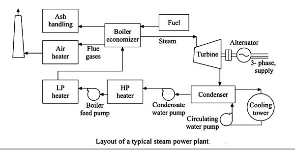
Ques 54. Carnot cycle comprised of:-
- Two identical processes and three constant pressure processes
- Two isothermal processes and the two constant pressure processes
- Two isentropic processes and two constant volume processes
- Two isentropic processes and two isothermal processes✓
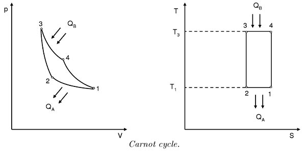
Let us explain the following terms:- Isentropic Process:- In thermodynamics, an isentropic process is an idealized thermodynamic process that is both adiabatic and reversible. Adiabatic process:- In ThermodynamicsAdiabatic process is a process in which there is no heat transfer take place into or out of the system i.e ΔQ=0. Isothermal Process: An isothermal process is one where the temperature of the system stays constant. A process is adiabatic in the following ways:- A cycle that continuously converts heat into work is called the power cycle. In a power cycle, the working fluid repeatedly performs a succession of processes. If the working fluid is alternately vaporized and condensed, then the cycle is called a vapor power cycle. The Carnot cycle is a theoretical idea that sets limits on the thermodynamic efficiency of heat engines. According to Carnot’s principle. 1. The efficiency of a reversible heat engine is always greater than that of an irreversible engine operating between the same two temperatures. 2. The efficiencies of all reversible heat engines operating between the same two temperatures are the same. Carnot cycle has the highest thermal efficiency. Only at the highest temperature is heat energy supplied and at the lowest temperature is heat energy removed. According to the figure, the Carnot cycle consists of two isothermals and two isentropic processes. Heat supply and removal occur only at the isotherms 3 -4 and 1-2. The resulting Carnot efficiency can be calculated from the temperatures T3 and T1 and is independent of the working medium:
Ques.55. Dependent sources are also called
- Uncontrolled source
- Time response elements
- Steady state elements
- Controlled sources✓
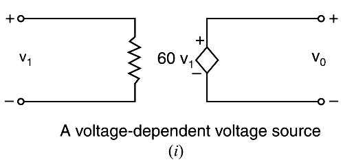
Independent and Dependent Voltage source Independent voltage source:- An independent voltage source is a two-terminal element (e.g a battery, a generator etc.) that maintains a specified voltage between its terminals. Independent voltage or current sources, do not depend on any other quantity in the circuit. Dependent sources:- A dependent voltage or current source is one that depends on some other quantity in the circuit which may be either a voltage or a current. For example, a voltage amplifier can be considered to be a dependent voltage source. It is because the output voltage of the amplifier depends upon another voltage i. e. the input voltage to the amplifier. Dependent sources are also called controlled sources because the value of the source is controlled either by a current in some element of the circuit or by a voltage between two terminals.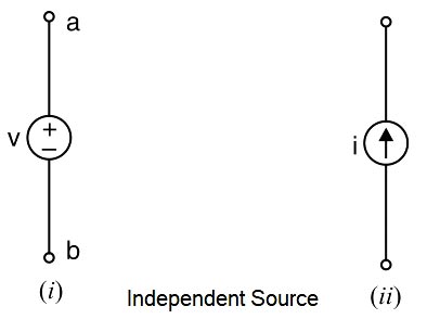
Ques.56. How many comparators would a 12-bit flash ADC require?
- 2512
- 3095
- 4095✓
- 4000
The number of comparators requires in 8-Bit flash ADC for n bit resolution is given as Number of comparator = 2n − 1 = 212 − 1 = 4096 -1 = 4095
Ques.57. Stability and transient response can be best determined by which of the following techniques?
- Root Locus✓
- Time response analysis
- Bode plot
- Nyquist plot
The nature of the transient response is closely related to the location of the closed-loop poles, it is very important to know how they move in the s-plane as the gain or some other parameter is varied. Root locus, a graphical presentation of the closed-loop poles as a system parameter is varied, is a powerful method of analysis and design for stability and transient response. The root locus is a powerful method of analysis and design for stability and transient response of the control systems. It brings into focus the complete dynamic response of the system and further being a graphical technique, an approximate root locus sketch can be made quickly. It gives information about the absolute stability as well as the relative stability of the system. For the closed-loop system to be stable, all the roots of the characteristic equation should fall in LHP(Left Half Plane). If the system is unstable, one could get information from root locus how it could be made stable, For a given value of K, the closed loop roots are easily determined from the root locus which is used to determine the transient response of the system for any input.
Ques.58. Voltage regulation of an ideal regulated power supply is measured to be equal to
- 2%
- 1%
- 100%
- 0%✓
Voltage regulation. The ratio of the change in dc voltage from no load to full load with respect to the full load voltage of a power supply is known as its voltage regulation. Voltage Regulation = (VNL − VFL) ⁄ VFL An ideal power supply is one for which VNL = VFL, it requires 0% regulation. In actual practice, however, no-load and full load respectively refer to the minimum and maximum limits of load current within which the regulation is required. The smaller the percentage regulation, the better is the supply. In a well-regulated power supply percentage, regulation should not be more than 1%.
Ques.59. _____ is supported from the cellings.
- Belt conveyor
- Roller conveyor
- Chain conveyor✓
- Trolly conveyor
The trolley conveyor consists of a series of trolleys supported from or within an overhead track. They are generally equally spaced in a closed-loop path and are suspended from a chain. Specially designed carriers can be used to carry multiple units of product. They have been used extensively in processing, assembly, packaging, and storage operations.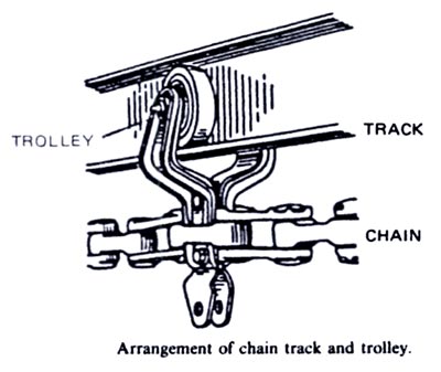
Ques.60. If a system is connected in the delta connection, how can be the total power output expressed as?
- 1/(√3VP.IP.Sinφ)
- (√3VP.IP.Cosφ)
- 1/(√3VP.IP.Cosφ)
- 3VP.IP.Cosφ✓
Whether a circuit is star connected or delta connected the Active power consumed in terms of phase voltage is given as P = 3VP.IP.Cosφ In terms of line voltage, the active power of star/delta will be P = √3VL.IL.Cosφ

