
UPPCL JE Electrical question paper with Explanation Set-2 -2018
Ques.1. Direction:- For the Assertion (A) and Reason (R) below, choose the correct alternative:-
Assertion (A):- 3 wire dc distribution system is preferred over 2 wire dc distribution system
Reason (R):- The 3 wire dc system of distribution is more safe
- Both A and R are true and R is not the explanation of A
- Both A and R are true and R is the correct explanation of A
- None of these
- A is true but R is false✓
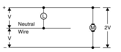
D.C. Distribution The electric power is almost exclusively generated, transmitted and distributed as a.c. However, for certain applications, d.c. supply is absolutely necessary. For instance, d.c. supply is required for the operation of variable speed machinery (i.e., d.c. motors), for electro-chemical work and for congested areas where storage battery reserves are necessary. For this purpose, a.c. power is converted into d.c. power at the sub-station by using converting machinery e.g., mercury arc rectifiers, rotary converters and motor-generator sets. The d c. supply from the sub-station may be obtained in the form of (i) 2-wire (ii) 3-wire for distribution. (i) 2-wire A.C system:- As the name implies, this system of distribution consists of two wires. One is the outgoing or positive wire and the other is the return or negative wire. The loads such as lamps, motors etc. are connected in parallel between the two wires as shown in Fig. This system is never used for transmission purposes due to low efficiency but may be employed for distribution of d.c. power. (ii) 3-wire d.c system:- It consists of two outers (lines) and a middle or neutral wire which is earthed at the sub-station. The voltage between the outers is twice the voltage between either outer and neutral wire as shown in Fig. The principal advantage of this system is that it makes available two voltages at the consumers’ terminals viz., V between any outer and the neutral and 2V between the outers. Loads requiring high voltage (e.g., motors) are connected across the outers, whereas lamps and heating circuits requiring less voltage are connected between either outer and the neutral. Due to the availability of two voltages, the 3-wire system is preferred over the 2-wire system for D.C distribution.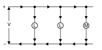
Ques.2. If the PIV rating of a diode is exceeded
- The diode conducts poorly
- The diode behaves like a tunnel diode
- The diode is destroyed✓
- The diode behaves like a capacitor
There are four diode ratings that apply in one way or another to all types of diodes and applications.
Ques.3. Which of the following defines power?
- Energy
- Watt
- The rate at which energy is used✓
- The rate at which energy is generated
The rate of doing work is called power. Or The rate at which energy is produced or utilized is called power. If W is the work done in time t (in seconds), such that P is the power, then P = W/t The SI unit of power is watt.
Ques.4. Which of the following is required in series RLC circuit to get Q>1
- XL < R
- XL > R✓
- XL = R
- None of these
The sharpness of the peak is measured quantitatively and is called the Quality factor, Q of the circuit. The quality factor relates the maximum or peak energy stored in the circuit (the reactance) to the energy dissipated (the resistance) during each cycle of oscillation. The quality factor is also the ratio of reactance and resistance. Quality factor = Reactance/Resistance = XC/R = XL/R To achieve the quality factor greater than 1 the value of reactance should be more than the value of resistance.
Ques.5. Which of the following comes under the category of systematic errors in an instrument?
- Blunders
- Gross errors
- Random errors
- Instrumental errors✓
Systematic errors describe errors in the output readings of a measurement system. Two major sources of systematic errors are system disturbance during measurement and the effect of environmental changes. Other sources of systematic error include bent meter needles, the use of uncalibrated instruments, drift in instrument characteristics, and poor cabling practices. Systematic errors can be further subdivided into two other kinds of errors: Instrumental errors are errors that come into play because of an inherent problem with the instrument itself. Many measuring devices are electromechanical devices and rely on springs magnets and gears. These parts will exhibit wear over time. As a result, they cannot function in the same way that they did when they were new. So, unless the instrument is carefully calibrated to account for these changes, error creeps in. Another common cause of instrument error it overloading the instrument. Environmental errors are caused by the surroundings in which the instrument is placed. Changes in temperature, humidity, pressure, and magnetic or electrostatic fields can all cause erroneous readings in instruments. Some instruments come with certain prescribed conditions in which they must be operated. For example, a sensitive scientific balance requires that it is placed on a hard level surface in order to provide correct readings. In addition, any vibration transmitted to the instrument will also distort the reported weight. As a result, these instruments are often placed on carefully prepared surfaces (such as heavy slabs of marble) to minimize these environmental sources of error.
Ques.6. Which of the following has the highest moderating ratio?
- H2O
- D2O✓
- Helium
- Carbon
The moderating ratio is the ratio of the macroscopic slowing down power to the macroscopic cross-section for absorption. The higher the moderating ratio, the more effectively the material performs as a moderator. Heavy water or D2O is a form of water that contains a larger than normal amount of the hydrogen isotope deuterium (2H or D, also known as heavy hydrogen). The D2O has the highest moderating ration of around 5000 to 7000 Helium has a moderating ratio of around 51. Water has a moderating ratio of 72. The moderating ratio of carbon is 220
Ques.7. Which of the following materials has susceptibility independent of temperature?
- Ferromagnetic
- Ferrimagnetic
- Paramagnetic
- Diamagnetic✓
The magnetic susceptibility expresses the responsiveness of a material to the applied magnetic field. Thus the greater the value of susceptibility of a material the greater will be its intensity of magnetization i.e., more easily it can be magnetized. Diamagnetic materials are materials with relative permeabilities slightly smaller than 1 (μr < 1). This class includes important materials such as mercury, gold, silver, copper, lead, silicon, and water. The relative permeability of most diamagnetic materials varies between 0.9999 and 0.99999 (susceptibility varies between (-10-5 and -10–4), and for most applications, they may be assumed to be nonmagnetic. An interesting aspect of diamagnetism is the fact that the magnetic flux density inside the diamagnetic material is lower than the external magnetic field. If we place a piece of diamagnetic material over a permanent magnet, the magnet will repel the diamagnetic material, as shown in Figure. Since the magnet and the equivalent magnetic field (due to the magnetization of the diamagnet material) oppose each other, the diamagnetic material is always repelled from the magnetic field in the same way that two magnets repel each other when their magnetic flux densities oppose each other. However, this force is extremely small for diamagnetic materials, except superconductors, in which it is very large. This repulsion is the reason why a permanent magnet floats above a superconducting material. The induced magnetic moments in atoms of a diamagnetic substance is not affected by the thermal motion of the atoms. For this reason, diamagnetism is independent of temperature.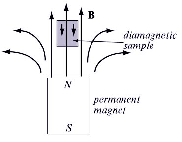
Ques.8. Which of the following material is a source of piezoelectric?
- Ceramic
- Lead alloy✓
- Lead Zirconate Titanate
- Quartz
Piezoelectric Effect is the ability of certain materials to generate an electric charge in response to applied mechanical stress. One of the unique characteristics of the piezoelectric effect is that it is reversible, meaning that materials exhibiting the direct piezoelectric effect (the generation of electricity when stress is applied) also exhibit the converse piezoelectric effect (the generation of stress when an electric field is applied). The most used piezoelectric materials are PZT, a ceramic containing lead titanate and lead zirconate and PZLT, a ceramic of lead-lanthanum-zirconate-titanate. Natural piezoelectric materials such as quartz (SiO2) and Rochelle salt (NaKC4H4O6–4H2O) are also used for piezoelectric transducers.
Ques.9. Which of the following materials follow magnetic anisotropy?
- Ferromagnetic✓
- Ferrimagnetic
- Paramagnetic
- Diamagnetic
Anisotropy is a term used in various scientific disciplines to indicate that certain properties of matter vary with the direction from which they are measured. Magnetic anisotropy is the directional dependence of a material’s magnetic properties. Ferromagnetic is the most useful magnetic materials. These derive their name from iron (Ferrum) as the most common of ferromagnetic materials. The relative permeability of ferromagnetic materials is much larger than 1 and can be in the thousands or higher. Some typical ferromagnetic materials are iron, cobalt, and nickel. Ferromagnetic materials tend to magnetize in the direction of the magnetic field and some of them retain this magnetization after the external magnetic field has been removed. When they do so, and the magnetization is permanently retained, the material becomes a permanent magnet. An additional important property of ferromagnetic materials is the dependence of magnetization on the level of the external field. Thus, magnetization in ferromagnetic materials is a nonlinear process. It has been observed that in single-crystal magnetic materials such as iron, the magnetic properties depend on the direction in which they are measured, i.e., iron exhibits preferred directions of magnetization. When the external field is absent, the spontaneous magnetization takes up a specific direction with respect to the crystal axis. The result is that one domain cancels the elect of the other so that the net magnetic moment in the material is zero. Therefore, a ferromagnetic material does not exhibit magnetism in its normal state. In iron, there are six equivalent preferred easy directions, one of the cube edges. This phenomenon is called magnetocrystalline anisotropy.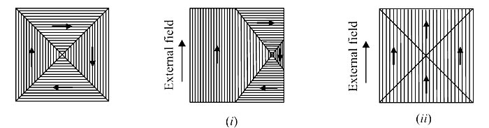
Ques.10. Which of the following terms is analogous to conductivity?
- Inductance
- Permeability✓
- Retentivity
- Resistivity
Conductivity is analogous to permeability. Conductivity is the measure of the ease at which an electric charge or heat can pass through a material. Permeability (electromagnetism), is the degree of magnetization of a material in response to a magnetic field.

