
Ques 66. A radio transmitter is an equipment:
- For receiving R.F signal
- For generating modulated radio frequency waves✓
- For amplifying R.F signal
- For generating the carrier wave
In electronics and telecommunications, a transmitter or radio transmitter is an electronic device that produces radio waves with an antenna. The transmitter is the key component of any radio broadcast. It takes your broadcast signal, encodes it, and transmits as radio waves that can be picked up by any receiver.
Ques 67. Negative feedback
- Increase the gain of amplifier
- Decrease the gain of amplifier
- Increase the gain and bandwidth of the amplifier
- Decrease the gain and increase the bandwidth of the amplifier✓
The amount of feedback (1 + Aβ) is also called the de-sensitivity factor. Noise Reduction: Negative feedback when used in amplifiers increases the signal the noise ratio or causes a reduction in noise. Non-linear Distortion: Reduction Application of negative feedback to amplifiers causes the amplifier characteristics to be less non-linear or more linearized and the distortion gets reduced by a factor of 1/(1 + Aβ). Increase in Input Impedance: Negative feedback increases the input impedance of amplifiers which is generally preferred in multistage amplifiers to reduce the loading effect.
Ques 68. Three-phase step-up transformer is installed at the powerhouse, then the transformer is used at the receiving end
- Delta – Delta connection
- Star – Star connection
- Star – Delta connection✓
- Delta – Star connection
In star connection, line and phase currents are the same but line voltage is √3 times the phase voltage. In the delta connection, line and phase voltages are same but the line current is √3 times the phase current. However, the power in both connections is same, that is √3VLIL cosφ. The star-delta transformer has the following advantages: The star-delta transformer has the following disadvantage: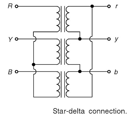
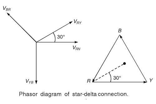
Advantages of Star-Delta Connection
Ques 69. When biased correctly, the Zener diode
- Acts as a fixed resistance
- Has a constant voltage across it✓
- Has a constant current passing through it
- Never Overheats
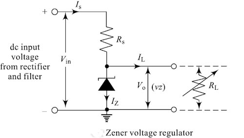
Zener diodes are similar to conventional diodes when they are forward biased When they are reverse biased, no conduction takes place until a specific value of reverse breakdown voltage (or “zoner” voltage) is reached. The Zener is designed so that it will operate in the reverse breakdown region of its characteristics curve. A properly doped junction diode that has sharp reverse breakdown voltage is called a zener diode. The reverse breakdown of Zener voltage or avalanche breakdown depends upon the amount of doping. If the diode is heavily doped depletion layer will be thin and consequently, the breakdown of the junction will occur at a lower reverse voltage. On the other hand, a lightly doped diode has a higher breakdown voltage. When used as a voltage regulator the zoner diode is reverse biased so that it will operate in the breakdown region. In this region, changes in current through the diode have little effect on the voltage across it. The constant-voltage characteristic of a Zener diode makes it desirable for use as a regulating device. From the VI Characteristics of Zener diode, we can see that the Zener diode has a region in its reverse bias characteristics of almost a constant voltage regardless of the current flowing through the diode This voltage across the diode called Zener voltage VZ remains nearly constant even with changes in current through the diode caused by variations in the supply voltage or load. This ability of the diode to regulate the source voltage can be best utilized in stabilizing a voltage source against supply or load variations. The diode will continue to regulate until the diode current falls below the lZmin ) value, a minimum value that keeps the diode in the reverse breakdown region. The resistor RS is connected in series with the Zener diode to limit the current flow with the output from the voltage source Vin being connected across the combination while the stabilized output voltage VO is taken across the Zener diode. The Zener diode is connected across the load with its cathode terminal connected to the positive rail of the dc supply so it is operating in its reverse-biased condition. The series resistor RS is so selected as to limit the current flowing in the circuit and hence the Zener diode well within maximum value lZmax. When the load resistance RL is very high, there is minimum current flowing through RL (no-load current IL = minimum or 0) and all the circuit current passes through the Zener diode which is lZmax) and dissipates maximum power in Zener. Care must be taken when selecting the appropriate value of resistance that the Zener maximum power rating is not exceeded under this “no-load” condition. When the load resistance RL is very low there is maximum current flowing through RL (full-load current IL = maximum) and only a small current passes through the Zener diode which is lZmin. Care again must be taken when selecting the appropriate value of resistance so that the stabilization of the voltage is effective and the Zener current must stay above this value operating the diode within its breakdown region at all times. In order to achieve this, both RS and RL should be properly selected. For e.g, A Zener diode that breaks down at 5V will have 5V across it even if you apply 12v to it. The remaining 7v will be across the resistor in series (Rs). So, any load(resistance RL) parallel to the Zener diode will have that constant 5v across it. Hence you get a constant voltage source.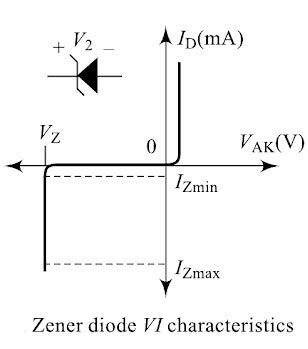
Ques 70. Induced draft fans are located at
- The top✓
- The bottom
- In the middle part
- Can be anywhere, in the cooling tower
Draft in a heating system refers to the pressure difference which causes a current of air or gases to flow through a combustion chamber, flue, or chimney. A natural draft is a draft obtained without any mechanical means. It is the heat of the combustion processes that create the differential pressure causing the draft. The mechanical draft is created by fans that either force or pull the air or combustion products through the system. Basically, there are two types of the draft fan Forced Draft fans suck air from the atmosphere, for providing the required quantity of hot air to the furnace for smooth and uniform combustion of fuel. they handle cold air. So they need low maintenance, consume less power (as pointed out, cold air has high density) and therefore their operating costs are low. The number of FD fans used is generally less than the number of ID fans. FD fan is placed before the boiler & forces the air to the boiler. Induced Draft produces pressure lower than the atmospheric pressure in the system or we may say that the ID fan will produce the negative pressure in the furnace to remove the flue gases from the furnace via electrostatic precipitators and to push the flue gases to the chimney. The counterflow (conventional) type of induced-draft tower has the fan located at the top.
Ques 71. In a thyristor the magnitude of the anode current will:
- Increase if gate current is increased
- Decreased if gate current is decreased
- increased if gate current is current
- Not change with any variation in the gate current✓
Things to Rember to understand the question. CURRENT RATINGS Latching Current (IL) The latching current is the minimum value of anode current to trigger or turn ON the thyristor from its OFF state to ON state even after the trigger pulse is removed. To trigger an SCR, the anode current must be build-up to the latching current before the gate pulse is removed. Holding Current (IH) The holding current is the minimum value of the anode current to hold the thyristor in the ON state. During turn OFF, the anode current should be below the holding current. Usually, the value of holding current is in milliamperes. Gate Current (Ig) The gate current is required at the gate of the thyristor to turn ON. There are two types of gate current: minimum gate current Igmin and maximum gate current Igmax. Igmin is the minimum value of gate current which is required at the gate to trigger the thyristor from its OFF state to ON state and its value depends on the rate of rise of current. Igmax is the maximum value of gate current that can be applied to the device for turn-on without damaging the gate. The turn-ON time of the thyristor reduces with the increase of gate current. The thyristor is a four-layered semiconductor that has three terminals. Current passes from the anode to the cathode when the device is turned on. It is turned on (triggered) by applying a small current, the gate current, through the gate to the cathode and when the anode current is above a specified parameter value called the latching current. On removal of the gate current, a thyristor will stay on if the anode current is above the device. Thus from the above discussion, it is clear that the gate current is independent of the anode current. In conduction mode, anode current has to be limited only by the load impedance. If the load impedance is increased gradually, the anode current gradually falls. If the anode current reduces to a value below the holding current,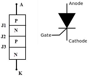
Ques 72. Brass is an alloy of
- Copper and Zinc✓
- Lead and Zinc
- Zinc and Tin
- Tin and Lead
Brass is a metallic alloy that is made of copper and zinc. 63% Tin, 37% Lead is eutectic and melts at a single point, used often used in electronics.
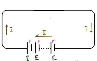
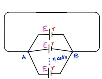
Ques 73. When cells are arranged in parallel:
- Current capacity increase✓
- Current capacity decreased
- The E.M.F increases
- The E.M.F decrease
As we know that in the series circuit the current remains the same and in the parallel circuit the voltage remains the same. Now consider the series circuit in which all the cells are connected in series. If there is “n” number of cells then the total EMF is nE. Now all the battery has total internal resistance therefore if n cell is connected in series than the total internal resistance will be “Rn” Now total current in the circuit is I = nE/nR = E/R When n number of cells are connected in parallel then total EMF is equal to E (since in parallel circuit voltage remains same). Internal resistance in parallel = R’ = R/n Total current in paralle circuit = I = nE/R Now consider 3 cell each of 2V having internal resistance of 0.1 ohm Current in series = I = E/R = 2/0.1 = 20A Current in parallel = I = nE/R = 60A Hence current capacity increase in the parallel.WHEN THE CELL ARE CONNECTED IN SERIES
WHEN THE CELL ARE CONNECTED IN PARALLEL
Ques 74. A capacitor opposes
- Change in current
- Change in voltage✓
- Both of the above
- None of the above
A capacitor opposes the change in voltage. Assume initially the capacitor has no charge which means both plates are neutral (each plate has an equal number of protons and electrons). If a battery is connected to a parallel plate capacitor, the positive terminal of the battery forcibly attracts the electrons from the capacitor plate A and the negative terminal of the battery will send the electrons to capacitor plate B. Initially, as time t is very small current is large(by I=Q/t) but when time passes the plate connected to the positive terminal becomes more positive and the plate connected to the negative terminal becomes more negative. Hence a steady state is reached after a certain amount of time(NOT INSTANTLY AFTER CONNECTING WITH BATTERY) when capacitor voltage becomes equal to the battery voltage. As we know current flows only when there is a potential difference, here the potential difference is zero at a steady state and so the capacitor acts as an open circuit in a steady state. In order to change the voltage in a capacitor, you have to put a charge into the capacitor because of Q=CV. If you want to change voltage instantaneously (meaning change voltage in zero time), you have to put all the required charges in zero time. That requires a very, very, very big current to move the charge in zero time. It is kind of difficult. Similarly, using the capacitor equation, I=C*dV/dt, we can see that to make an instantaneous change in the voltage (dt approaches zero), I approach infinity. Well, think of an empty bucket (capacitor); and you need to fill the bucket with water (water is the charge, and the water level is voltage). You can fill it with your pipe (the water flow rate is current). The bigger the pipe (the larger the flow rate or current), the faster you fill the bucket.,..but it will take time. In order to fill the bucket in zero time, you need a big pipe that carries an infinite flow rate.
Ques 75. A.C supply system compared to D.C supply
- Power Factor
- Reactive element
- Voltage drop
- Low cost of switching✓
Consumer’s Perspective:
For DMRC 2016 Solved Paper CLICK HERE
For DMRC 2015 Solved Paper CLICK HERE
For NMRC 2017 Solved Paper CLICK HERE
For SSC JE CONVENTIONAL Paper 2017 CLICK HERE
For SSC JE CONVENTIONAL Paper 2016 CLICK HERE

