
DMRC Junior Engineer Previous Year Electrical Question Paper with explanation and Solution -2017
Ques 1. In measuring instrument damping force can be produced by
- Supply current
- Moving Coil
- Eddy current✓
- Commutator
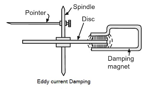
Basically, there are three types of Force or torque that act upon the Measuring Instrument Deflecting Torque: In order to move the pointer from its zero position on the scale deflecting torque is required. The deflecting torque works on the moving system to which the pointer is attached. Obviously, the magnitude of deflecting torque produced is proportional to the magnitude of the quantity being measured, say, the current I flowing through the instrument. A deflecting torque is required to overcome the inertia, damping effect, and controlling effect of the moving system. This deflecting torque can be produced by any of the effects of current (or of voltage) such as Controlling Torque: With the help of the deflecting torque, the pointer deflection will take place on the calibrated scale but to stop the pointer at the definite position, controlling torque (Tc.) comes into action. As the deflection of the pointer increases, the controlling torque also increases and stops the pointer at the measured value. Controlling torque is also known as restoring torque i.e., it brings back the pointer to its zero position when deflecting torque is withdrawn. The pointer attains a steady position when controlling torque becomes numerically equal to deflecting torque i.e., Tc = Td Spring control and gravity control are used for controlling torque. Damping Torque: At the final deflected position, when the deflecting and controlling torques are equal, the pointer starts oscillating owing to its inertia and therefore, cannot immediately settle at its final deflected position. If no extra force is provided to dampen these oscillations, the moving system will take considerable time before coming to settle to the final deflected position. This is especially undesirable if the number of readings to be taken is quite large. Air friction, Eddy current damping, and Hydraulic damping are used in damping torque. Eddy Current Damping: This is the most effective way of providing damping. It is based on Faraday’s law and Lenz’s law. When a conductor moves in a magnetic field cutting the flux, e,m.f. got induced in it. And the direction of this e.m.f. is such as to oppose the cause producing it. This force always acts in opposite direction to that of the cause producing it, that is, motion according to Lenz s law. This provides necessary damping torque. The magnitude of damping torque is directly proportional to the speed of the moving system. In this method, a thin disc is connected to the spindle. The disc is allowed to move along with the spindle inside the magnetic field provided by a permanent magnet. The movement of the disc causes an eddy e.m.f to get induced in it causing an eddy current to flow. The flux set up eddy current interacting with the magnetic field exerts a force on the disc. The force of Lenz’s law opposes the movement of the disc. The necessary damping torque is provided.
Ques 2. In the case of Zero Power factor leading load on the alternator, the effect of armature reaction is
- To decrease the induced EMF
- To cross-Magnetize
- To increase Induced EMF✓
- To de-magnetize
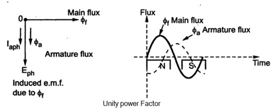
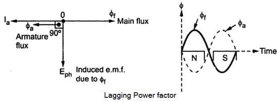
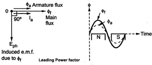
The effect of the armature flux on the main flux affects its value and the distribution called armature reaction. When the generator supplies a load at leading power factor the armature reaction is partly magnetizing and partly cross-magnetizing; At zero power factor leading load, it is purely magnetizing and the induced emf will get increased The effect of the armature flux not only depends on the magnitude of the current flowing through the armature winding but also depends on the nature of the power factor of the load connected to the alternator Consider a purely resistive load connected to the alternator, having a unity power factor. As induced e.m.f Eph drives a current Iph and load power factor is unity, Eph and Iph are in phase with each other. If φf is the main flux produced by the field winding responsible for producing Eph then Eph lags φf by 90°. Now current through armature Ia produces the armature flux say to,, So flux φa, and la are always in the same direction. It can be seen from the phasor diagram that there exists a phase difference of 90°between the armature flux and the main flux. From the waveforms, it can be seen that the two fluxes oppose each other on the left half of each pole while assisting each other on the right half of each pole. Hence average flux in the air gap remains constant but its distribution gets distorted. Hence such distorting effect of armature reaction under unity p.f. the condition of the load is called the cross magnetizing effect of armature reaction. Due to such distortion of the flux, there is a small drop in the terminal. Consider a purely inductive load connected to the alternator having zero lagging power factor. This indicates that Iph driven by Eph lags Eph by 90° which is the power factor angled. Induced e.m.f. Eph lags main fluxes φf by 90° while φa is in the same direction as that of Ia. It can be seen from the phasor diagram that the armature flux and the main flux art exactly in the opposite directions to each other. So armature flux tries to cancel the main flux Such an effect of armature reaction is called the demagnetizing effect of the armature reaction. As this effect causes the reduction in the main flux, the terminal voltage drops. This drop in the terminal voltage is more Man the drop corresponding to the unity p.f. load. Consider a purely capacitive load connected to the alternator having zero leading power factor. This means that armature current Iaph driven by Eph leads Eph by 90° which is the power factor angle φ. Induced e.m.f. Eph lags φf by 90° while Iaph and φa, are always in the same direction. The armature flux and the main field flux are in the same direction i.e. they are helping each other. This results in the addition of the main flux. Such an effect of each armature reaction due to which armature flux assists field flux is called the magnetizing effect of the armature reaction As this effect adds the flux to the main flux, greater e.m.f. gets induced in the armature Hence there is an increase in the terminal voltage for leading power factor loads. For intermediate power factor loads i.e. between zero lagging and zero leading the armature reaction is partly cross magnetizing and partly demagnetizing for lagging power factor loads or partly magnetizing for leading power factor loads.Unity Power Factor Load (Cross-Magnetizing)
Zero Lagging Power Factor Load (Demagnetizing)(Over-excited)
Zero Leading Power Factor Load (Magnetizing) Under-excited
Ques 3. An electric short-circuit is characterized by
- Zero Resistance✓
- Infinite Resistance
- Medium Resistance
- Large Resistance
A short circuit (sometimes abbreviated to short or s/c) is an electrical circuit that allows a current to travel along an unintended path with no or a very low electrical impedance. This results in an excessive amount of current flowing into the circuit. According to Ohm’s Law, voltage equals current times resistance. Therefore, when the resistance becomes very low and the voltage does not change, the current becomes very high. Ohm’s Law: V=IR. If R= zero, as is the case for an ideal short-circuit, there must be zero voltage across the circuit letting the current through. As we know that potential differences must be needed to flow current. So, if there is no potential difference between the two points of a short-circuit, how can current flow? The answer lies in the fact that an electrical conductor has some resistance, however small. Therefore there will be some small voltage across the short circuit. Although the voltage may be very small, the resistance of the “short” is also very small- near zero, therefore large currents can flow. (In any case, if you agree that there can be a resistance of zero ohms, then you need to accept that there can be zero volts across it regardless of the current flowing through it.)
Ques 4. The motor having the smooth chrome steel cylinder with no rotor winding is
- Hysteresis Motor✓
- Universal Motor
- Repulsion Motor
- Reluctance Motor
Hysteresis motor is the synchronous motor that does not require any d.c. excitation to the rotor and it uses non-projected poles. Hysteresis motors start by virtue of the hysteresis losses induced in the rotor by the rotating magnetic field produced by the stator windings. It consists of a stator that carries main and auxiliary windings so as to produce a rotating magnetic field. The stator can also be a shaded pole type. The rotor is the smooth cylindrical type made up of hard magnetic material like chrome steel or alnico for high retentivity (it is the capacity of an object to retain magnetism after the action of the magnetizing force has ceased. This requires selecting a material with a high hysteresis loop area. The rotor does not carry any winding. Note:– The reluctance motor also doesn’t carry any winding on the rotor side but it contains short circuit copper and aluminum bar like a squirrel cage induction motor.
Ques 5. The reluctance of the stator winding of an alternator at the instant of the short circuit at its terminals is called.
- Synchronous Reactance
- Per-unit Reactance
- Transient Reactance
- Sub-transient Reactance✓
The concept of Subtransient, Transient, and Steady-State arises in case of a fault in an Alternator. Let us assume a sudden short circuit in the three-phase of an alternator. The fault current will flow in all three phases of an alternator.
The sub-transient reactance is an impedance value that entirely neglects the resistance component.
current from the first few cycles up to about 30 cycles after the short-circuit occurs (depending upon the design of the machine). This value is often used in voltage regulation studies.
Ques 6. The electric charge of a body is a condition due to
- Deficiency or excess of neutron
- Excess of Electron
- Deficiency of electrons
- Deficiency or excess of electron✓
In an electric conductor, the electric charge flows front one end to another end of the conductor, only when an electric potential difference exists between the two ends of the conductor Thus an electric potential difference is a condition required for a conductor to have an electric charge.
Ques 7. The RMS value of the Half wave rectifier is
- 0.637 Im
- 0.5 Im✓
- 0.707 Im
- 0.8 Im
RMS Value of a half-wave rectifier is Vrms = Vm/2 RMS current of Hald wave rectifier Irms = Im/2 Average voltage or current of half wave rectifier is = Vavg = Vm/π or Im/π Note: RMS value of current or voltage of full wave rectifier is VRMS = Vm/√2 or Im/√2 Average value of current or voltage of full-wave rectifier is Vavg = 2Vm/π or 2Im//π
Ques 8. In magnetism the equivalent of unit N/wb is
- A/m✓
- J/wb
- Tesla
- V/cm
Magnetic Field Strength (H) gives the quantitative measure of the strongness or weakness of the magnetic field. The magnetic field at a given point is specified by both a direction and a magnitude and is described by magnetic field intensity, H. The magnetic field intensity, H. at any point is defined as the force experienced by a north pole of one Weber placed at that point. In other words, it is defined as the magnetomotive force per unit length produced by the steady current in a magnetic circuit. Its unit is Newton per Weber (N/Wb) or Ampere per meter (A/m) or Ampere-turn per meter (AT/m). Note:- Tesla is the unit of magnetic field density
Ques 9. A PMMC can be used as Ammeter by using:
- Series Inductor
- Shunt Inductor
- Shunt Resistors✓
- Series Resistors
CURRENT MEASUREMENT Based on the PMMC instrument, an ammeter can be constructed for the measurement of dc current. the simple arrangement of a dc ammeter is the shunt resistance Rsh along with the meter from the ammeter. The moving coil instruments can carry the maximum current of about 50 mA safely and the potential drop across the moving coil is about 50 mV. However, in practice, heavy currents and voltages are required to be measured. Therefore, it becomes necessary that the current and voltage being measured be reduced and brought within the range of an instrument. There are four common devices used for extending the range of the instruments, namely shunts, multipliers, current transformers, and potential transformers. The extension of the range of current and potential transformers is employed for the measurement of very high AC currents and voltages in a power system. Here, the terminals AB forms the arm through which the current is to be measured. Im is the current through the meter, R is the resistance of the meter, Rsh is the shunt resistance and I is the current under measurement. The low-value shunt connects in parallel to the ammeter because of which the voltage drops across the meter and the shunt remain the same.A significant portion of the measurand current passes to the shunt because of the low resistance path and few amounts of current pass through the ammeter. Let I= current to be measured. Rsh = shunt resistance, Since the Rsh and meter are in shunt the voltage across them will be same and is given by Ish x Rsh = Im x Ram we have, I = Im + Ish Ish = I – Im (I – Im)Rsh = Im x Ram IRsh = Im(Rm + Rsh) I/Im = (Rm + Rsh)Rsh The ratio of the total current I to be measured to the full-scale deflection current Im is known as the multiplying factor of the shunt or instrument constant. It may be denoted by M.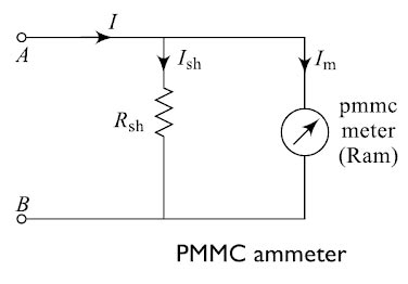
Im = full-scale deflection current of ammeter
Ish = shunt current
Ram = resistance of PMMC; m
or
Ques 10. For an RLC series circuit, the current resonance is;
- V/L
- Minimum
- Zero
- Maximum✓
In the RLC series circuit the total impedance of the series LCR circuit is given as Z2 = R2 + (X1 – X2)2 where X1 is inductive reactance and X2 is capacitive reactance. At a particular frequency (resonant frequency), we find that X1=X2 because the resonance of a series RLC circuit occurs when the inductive and capacitive reactances are equal in magnitude but cancel each other because they are 180 degrees apart in phase. Therefore, the phase angle between voltage and current is zero and the power factor is unity. Thus, at the resonant frequency, the net reactance is zero because of X1=X2. The circuit impedance Z becomes minimum and is equal to the resistance R. “Since the impedance is minimum, the current will be maximum”. Hence electrical resonance is said to take place in a series LCR circuit when the circuit allows maximum current for a given frequency of alternating supply at which capacitive reactance becomes equal to the inductive reactance.

