Ques.11. For Modern alternator, what will be the specific value of SCR?
- 3/2
- 1/2✓
- 1/6
- 1/5
The ratio of field current required to produce rated voltage on open-circuit to the field current required to circulate rated current on short-circuit in armature while the machine is driven at synchronous speed is called short-circuit ratio (SCR) of a synchronous machine. SCR = Field current for rated voltage at no load ⁄ field current for rated armature current when shorted SCR is just reciprocal of per unit synchronous reactance Xs of the machine i.e SCR = 1/Xs. The value of synchronous reactance depends upon saturated conditions of the machine whereas, SCR is specific and defined at the rated voltage. Significance of SCR Smaller is the value of SCR, larger is the value of synchronous reactance which limits the short circuit current to the smaller value. But it causes difficulty during parallel operation of the machines owing to the smaller value of synchronizing power. The short circuit ratio is the measure of the alternator’s sensitivity to load changes. Machines with higher SCRs are larger in size, weigh more and also cost more. Their voltage regulation is smaller than those of machines with smaller SCRs. Conversely, alternators with lower SCRs have larger synchronous reactances and higher voltage regulations. Hence, they require quick acting; field control devices to maintain a fairly constant output voltage The larger value of SCR increases the stability of the machine and improves its voltage regulation. Usually, the SCR of high-speed non-salient pole alternators lies between 0.5 and 0.75 whereas it lies between 1.0 and 1.5 for low-speed salient pole type alternators. Therefore, the salient pole type alternators are more stable than non-salient pole type alternators.
Ques.12. To save energy during braking which type of Braking is used?
- Regenerative✓
- Plugging
- Dynamic
- All of these
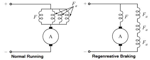
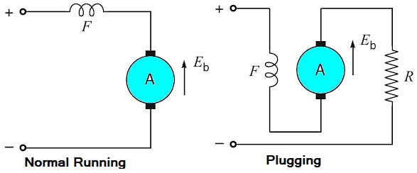
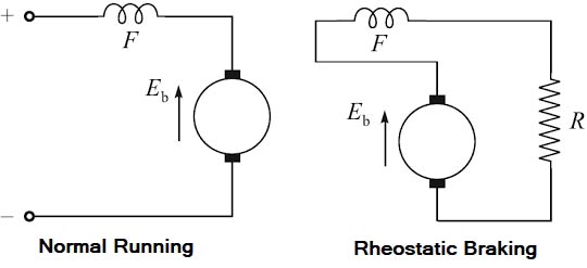
The process of bringing the motor to rest within the predetermined time is known as braking. A good braking system must have the following features: Braking applied to bring the motor to rest position is of two types and they are: 1. Electric braking. Mechanical braking In this process of braking, the kinetic energy of the rotating parts is dissipated in the form of heat by the brake shoes of the brake lining that rubs on a wheel of vehicle or brake drum. Electric braking In this process of braking, the kinetic energy of Be rotating parts of the motor is converted into electrical energy which in turn is dissipated as heat energy in a resistance or in sometimes, electrical energy is returned to the supply. Here, no energy is dissipated in brake shoes. Electric braking can be applied to the traction vehicle, by any one of the following methods, namely: 1. Plugging The disadvantages of this method are: 1. The kinetic energy of the motor is dissipated in the external resistance in the form of heat. So, this method of braking is inefficient. 2. The braking in this method fails in case of failure of the supply. The disadvantage of the method is that the kinetic energy of the motor is dissipated as heat in the resistance and it is a wastage. The armature current and so the magnetic field changes with the change in speed. Therefore, the speed-torque curve is not linear in the case of the series motor.
2. Mechanical braking.TYPES OF ELECTRIC BRAKING
2. Rheostatic braking.
3. Regenerative braking.Regenerative braking
Plugging
Rheostatic braking
Ques.13. For the protection of power station buildings against direct strokes the requirements are
- Interception and conduction
- Interception, conduction, and dissipation✓
- Interception, conduction, dissipation, and reflection
- None of these
Protection Against Lightning Proper protection must be provided to the power stations, substations, overhead transmission lines from the direct lightning strokes while the electrical apparatus must be protected from indirect strokes in the form of travailing waves. the lightning strokes can cause severe damage than other types of switching surges or transients. Hence protection against lightning strokes is an important consideration in the system design. Protection of Generating Stations and Substations Against Direct Strokes Generally the generate stations are housed In big buildings while the substations are housed in switchyard or outdoor. To protect a structure against direct strokes, three requirements must be fulfilled. These involve: (a) an object in good electrical connection with the earth to attract the leader stroke. (b) a path joining this object to earth of a low impedance. (c) a low resistance connection with the earth. For INTERCEPTION OF LIGHTNING STROKE, the upper portion of a metal structure, or a separate metallic system (often called shield) mounted on the structure may be used. A particular shield configuration is in the form of masts or Overhead ground wires. This provides good shielding to the effect that out of 1000 strokes on the shield or shielded object, 999 will terminate on the shield and only one on the protected object. This is called 0.1% exposure. Such is the effect of good shielding. For CONDUCTION OF LIGHTNING CURRENT the requirements are: (i) low resistance (ii) low reactance, since in the long circuitous line the rapid rate of rise of lightning current may produce high voltage due to high inductance. (iii) Sufficient clearance from any other conducting object.
Ques.14. Which among the following is termed as the drift velocity of the charge carrier per unit electric field?
- Resistivity
- Current density
- Mobility✓
- Relative permittivity
Drift velocity:- The average velocity of the charge carrier in an electric field is known as drift velocity. Mobility:- The electron mobility characterizes how quickly an electron can move through a metal or semiconductor when pulled by an electric field. The mobility of a charge carrier is defined as the drift velocity acquired by a per unit applied the electric field. or It may also be defined as the ratio of average drift velocity of the charge carriers to the applied electric field. The mobility of a charge carrier increases with the increase of electrical conductivity of the specimen. Electron mobility is almost always specified in units of cm2/(V·s (volt second))
Ques.15. Which among the following oscillator’s output depends on nonlinear characteristics of the circuit.
- Relaxation oscillator✓
- Colpitts oscillator
- Wien bridge oscillator
- Crystal oscillator
An oscillator is a system consisting of active and passive circuit elements to produce a sinusoidal or other repetitive waveforms at the output without the application of an external input signal. It transforms the dc power from the supply source to the ac power in the load. Thus the function of an oscillator id opposite to that of a rectifier that converts ac power into D.C power. Oscillators find applications in radio and TV transmitters and receivers, and in the laboratory teat equipment. Depending on the type of the output waveform, oscillators are classified as sinusoidal (or harmonic) oscillators and relaxation oscillators. If the generated waveform is sinusoidal or nearly so with a definite frequency, the oscillator is said to be a sinusoidal oscillator. If the output waveform is non-sinusoidal (such as square or sawtooth waveforms), the oscillator is termed a relaxation oscillator. NOTE:- The Colpitts oscillator is an electronic oscillator that use a combination of inductors (L) and capacitors (C) to produce an oscillation at a certain frequency. A Wien bridge oscillator is a type of electronic oscillator that generates sine waves. It can generate a large range of frequencies. A crystal oscillator is an electronic oscillator circuit that uses the mechanical resonance of a vibrating crystal of piezoelectric material to create an electrical signal with a precise frequency.
Ques.16. Which among the following configuration has both current and voltage gain?
- CC
- CB
- Both CB and CC
- CE✓
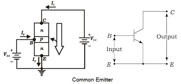
In this circuit the emitter terminal is common to both the input i. e. base-emitter circuit and the output i.e. the collector-emitter circuit and is grounded. The input (or emitter) circuit is forward biased by connecting the positive of the emitter-base battery VBB to the emitter terminal and the output (or collector) circuit is reverse biased by connecting the negative of the collector-emitter battery VCC to the collector terminal. So, output resistance is more than the input resistance. Out of the three transistor connections, the common emitter circuit is the most efficient. It is used in about 90 to 95 percent of all transistor applications. The main reasons for this are : High current gain In common emitter connection, Ic is the output current and IB is the input current. The collector current here is expressed as: Ic = βIB + ICEO As the value of β is very large, therefore, the output current IC is much more than the input current IB. This increases the current gain effectively. The current gain of CE arrangement ranges from 20 to High Voltage and Power Gain As we have seen above, CE arrangement has the high current gain. This is turn, increases the voltage and power gain of the CE circuit. In comparison to CB and CC circuits, the common emitter connection has the highest voltage and power gain. For this reason, the CE transistor connection is often used for amplifying purposes. [ninja_tables id=”27501″]
Where β = Current Gain
ICEO = Collector-Emitter current
500.
Ques.17. Which among the following is related to unsymmetrical faults?
- Double line to ground fault
- Single line to ground fault
- Line to Line fault
- All of these✓
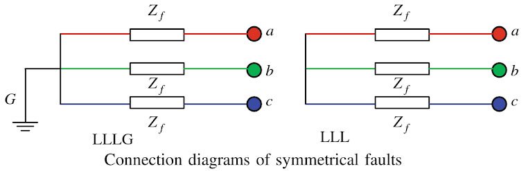
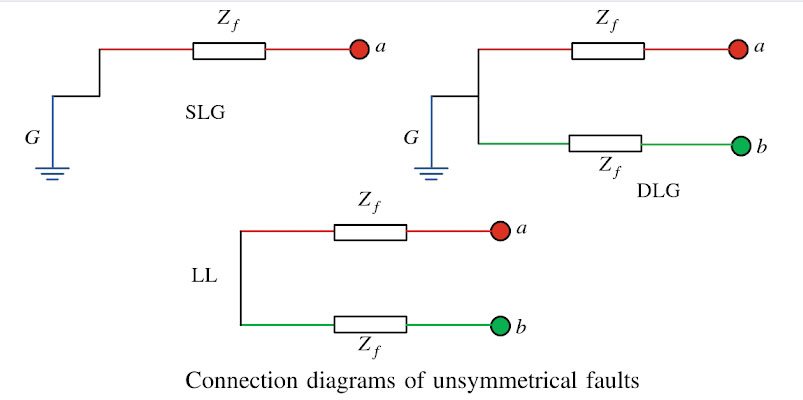
The fault in the power system is generally categorized into two type Symmetrical Fault The symmetrical faults are often known as balanced faults. In case of balanced faults, all three transmission lines are affected equally, and the system remains in the balanced condition. These types of faults are rare in the power system, and it contributes 2 % to 5 % of the total fault. These faults are easy to analyze. The symmetrical faults are classified as three lines to ground fault (LLLG) and three lines fault (LLL). The connection diagrams of symmetrical faults are shown in Fig. If the fault impedance, Zf = 0, then the fault is known as a solid or bolted fault. Unsymmetrical Faults The faults in the power system network which disturb the balanced condition of the network are known as unsymmetrical faults. The unsymmetrical faults are classified as the single line to ground faults (SLG), double line to ground faults (DLG 10%) and line to line faults (LL 15%). More than 90 % of faults occur in a power system are the single line to ground faults. The connection diagrams of different types of unsymmetrical faults are shown in Fig.
Ques.18. Which function is used to find the probability of an electron existing as a function of energy level?
- Gauss
- Geometric distribution
- Fermi-dirac✓
- Cumulative distribution
Fermi level is the energy which any electron possesses at 0° Kelvin. For P-type semiconductor, the Fermi-level lies above the valence band. For N-type semiconductor, the Fermi level lies below the conduction band.
For the n-type semiconductor, Fermi level goes down with an increase in temperature and with further increase in temperature it will come at the center of the forbidden energy gap. Thus at a higher temperature that n-type semiconductor behaves like an insulator.
For p-type semiconductor, Fermi level goes up with an increase in temperature and with further increase in temperature it will come at the center of the forbidden energy gap. Thus at higher temperature p-type semiconductors behave like an insulator.
Fermi-Dirac Function f(E)
Fermi-Dirac function f(E) gives the probability that a quantum state with energy E (electron volt) is occupied by an electron. It is also called Fermi-Dirac probability function. For a metal or semiconductor, we have
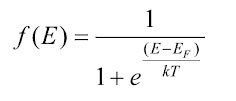
where,
E = Energy possessed by an electron in eV
k = Boltzmann constant
T= Absolute Temperature (in Kelvin)
EF = Fermi level for crystal, eV
At T= 0 Kelvin: (E = EF) condition not possible; hence, we get the following two condition
- If E > Ef
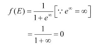
This indicates that there are no electrons available at 0 Kelvin With energies greater than EF (E > EF).
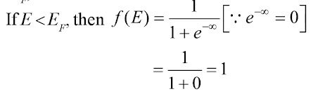
This indicates that at 0° Kelvin electrons exist with energy E < Ef.
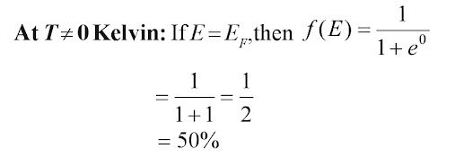
This indicates that when the temperature is other than 0° Kelvin then the chances of electrons existing with energy E = EF is 50 percent.
The main points are:
- In metals, f(E) = 1
- In the semiconductor, if the probability of an electron existing is f(E), then the probability of whole exit existing is 1 − f(E).
- Fermi-Dirac function is used to find the probability of an electron existing as a function of energy level.
- Fermi level EF represents the energy state with 50 percent probability of being filled if no forbidden band exists.
- At T = 0°, if E >> EF, then f(E) = 0. Thus, there is zero probability of finding an occupied quantum state of energy greater than Ef at 0°K.(ii) If E << EF‘ then f(E) = 1. Thus, all quantum levels with energy less than Ef are occupied at T= 0°K.
Ques.19. Select the dielectric constant of Silicon.
- 11.7✓
- 10
- 0.00105
- 35
Ques.20. Which configuration in Bipolar Junction Transistor is also known as Voltage follower circuit?
- Common Base
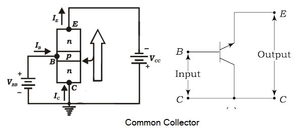
- Common Collector✓
- Common Emitter
- None of these
In common-collector configuration, the collector terminal of a transistor is connected as common terminal between input and output as shown in fig. The base and collector terminals are used to apply the input signal whereas the output signal is obtained. The CC configuration is also commonly known as the emitter follower or the voltage follower. This is because the output signal across the emitter is almost the replica of the input signal with little loss. In other words, There is no phase inversion between input and output in the emitter follower circuit.The output voltage is in phase with the input voltage and hence the voltage gain will be a maximum of one. The common-collector configuration is used primarily for impedance-matching purposes since it has a high input impedance and low output impedance, opposite to that of the common-base and common- emitter configuration.Common-Collector Configuration