Ques.41. The two transistor model of the SCR can be obtained by:-
- Bisecting the SCR vertically
- Bisecting the SCRs middle two layer
- Bisecting the SCR horizontally
- Bisecting the SCRs top two and bottom two layers✓
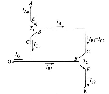
SCR is a unidirectional device and like a diode, it allows current to flow in one direction only. It can be used as a switch. The switching of SCR is controlled by the additional input called gate and biasing conditions. It can be used as a rectifier to convert AC signals to DC signals. Construction The SCR is a four-layer p-n-p-n device, where p and n layers are alternately arranged. The outer layers are heavily doped. There are three p-n junctions called J1, J2, and J3. The outer P-layer is called anode and outer n-layer is called cathode, middle P-layer is called the gate. The terminals are taken out from their layers. Anode must be positive with respect to the cathode so that SCR will be forward biased. To turn on an SCR, a current is to be passed through the gate terminal. Hence it is a current operated device. Two Transistor Model of SCR The operation of an SCR can also be explained in a very simple way by considering it in terms of two transistors. This is known as the two transistor analogy of the SCR. The SCR can be considered as an NPN and a PNP transistor, where the collector of one transistor is attached to the base of the other and vice versa. This model is obtained by splitting the two middle layers of the SCR into two separate parts. In the above figure, two middle layers of the SCR is split into two separate parts i.e PNP transistor T1 and NPN transistor T2. Collector current in the NPN transistor acts as the base current for the PNP, and analogously, the collector current of the PNP acts as the base current driving the NPN transistor. IA is the anode current IC is the cathode current IG is the gate current IE1 is the emitter current of the PNP transistor (T1) IE2 is the emitter current of the NPN transistor (T2) IC1 is the collector current of the PNP transistor (T1) IC2 is the collector current of the NPN transistor (T2) IB1 is the base current of the PNP transistor (T1) IB2 is the base current of the PNP transistor (T2) α1 is the current gain of the transistor T1 α2 is the current gain of the transistor T2 The sum of two collector currents is equal to the external circuit current Ia, entering at anode terminal A. ∴ Ia = IC1 + IC2 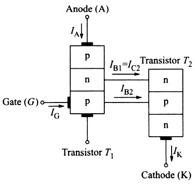
Ques.42. The current zero interruption, in oil and air blast circuit breaker, is achieved by
- Deionizing the oil with forced air
- Lengthening of the gap or cooling the blast effect✓
- Lengthening of the gap
- Cooling of the blast effect
Oil circuit breakers are the oldest type of circuit breakers which used oil as a dielectric or insulating medium for arc extinction. In oil circuit breaker the contacts of the breaker are made to separate within an insulating oil which has better insulating properties than air. Oil circuit breaker utilizes dielectric oil (transformer oil) for arc extinction. These circuit breaker can be employed for a voltage range of 33 kV to 22o kV and breaking capacity of 1500 MVA to 7500 MVA Air blast circuit breaker:- In this type of circuit breakers, the compressed air is used for the arc extinction. Hence it is called a compressed air circuit breaker. Those type of circuit breakers were employed in earlier days in indoor services for voltages ranging from 11 to 1100 kV with breaking capacities up to 25000 MVA. At high voltages, this type of circuit breakers is most suitable. In modern-day, the air blast circuit breaker is also employed in high voltage circuit in the outdoor switchyard. The air blast circuit breakers are preferred for arc furnace duty and traction system because they are suitable for repeated duty. These type of circuit breakers are finding their best application in systems operating in the range of 132 kV to 400 kV with breaking capacities up to 7000 MVA. After the occurrence of the fault, when the contacts of the CB begins to separate an arc is established in the contact gap. The two main causes responsible for generating arc between the contacts of a CB are as follows: Potential difference (PD) between the contacts: When the contacts have a small separation, the PD between them is sufficient to maintain the arc. One way to extinguish the arc is to separate the contacts to such a distance that PD becomes inadequate to maintain the arc. However, this method is impracticable in high voltage system where a separation of many meters may be required. Ionized particles between contacts: The ionized particles between the contacts tend to maintain the arc. If the arc path is deionized, the arc extinction will be facilitated. This may be achieved by cooling the arc or by bodily removing the ionized particles from the space between the contacts. Methods of Arc Extinction There are two methods of extinguishing the arc in CB viz. In this method, arc resistance is made to increase with time so that current is reduced to a value insufficient to maintain the arc. Consequently, the current is interrupted or the arc is extinguished. The principal disadvantage of this method is that enormous energy is dissipated in the arc. Therefore, it is employed only in DC CBs and low capacity AC CBs. The resistance of the arc may be increased by: Low Resistance or Current Zero Method This method is employed for arc extinction in AC circuits only. In this method, arc resistance is kept low until current is zero where the arc extinguishes naturally and is prevented from restriking in spite of the rising voltage across the contacts. All modern high-power AC CB employ this method for arc extinction. In an AC system, current drops to zero after every half cycle. At every current zero, the arc extinguishes for a brief moment. Now the medium between the contacts contains ions and electrons so that it has the small dielectric strength and can be easily broken down by the rising contact voltage known as restriking voltage. If such a breakdown does occur, the arc will persist for another half cycle. If immediately after current zero, the dielectric strength of the medium between contacts is built up more rapidly than the voltage across the contacts, the arc fails to restrike and the current will be interrupted. The rapid increase of dielectric strength of the medium near current zero can be achieved by
Ques.43. How is the voltage determined when the current and resistance are given?
- Divide the current resistance
- Subtract the current from the resistance
- Multiply the current resistance✓
- Add the current and the resistance
Ohm’s Law Ohm’s law states that electric current flowing through the conductor is directly proportional to the potential difference between its two ends when the temperature and other physical parameters of the conductor remain unchanged. Assuming (VAB) be the Potential difference between the two ends A and B of a conductor, with terminal A at the higher potential, current (I) being flowing through the conductor, we can write as per Ohm‘s law VAB ∝ I or VAB = R.I Hence to determine voltage the resistance is multiplied by the current
Ques.44. The apparatus used for switching, controlling, and protecting the electrical circuit and equipment is
- Conductor
- Diverter
- Switchgear✓
- Insulator
SWITCHGEAR DEFINITION:- Switchgear is a general term covering switching and interrupting devices that control, meter and protect the flow of electric power. or The apparatus used for switching controlling and protecting the electrical circuits and equipment is known as switchgear. The component parts include circuit breakers, instrument transformers, transfer switches, voltage regulators, instruments, and protective relays and devices. Switchgear subdivides large blocks of electric power and performs the following missions:
Ques.45. Which unit is used to measure the capacity of a battery?
- Watt
- Amper-Hour✓
- Volt-Ampere
- Ampere
The amount of energy that a battery can store is caged its capacitor. A water tank, for example, with a capacity of 8000 liters can hold at most 8000 liters. Similarly, a battery can only store a fixed amount of electrical energy, typically marked on the side of the battery by the manufacturer. Actually battery capacity is measured in the amount of charge it can hold. Now we know the current is charge per unit time, therefore the product of current and time gives us the charge. That is why battery capacities are measured in milliampere-hour in case of cellphone batteries or ampere-hour in case of automotive batteries. Battery capacity = charge stored = current x time or amp-hr. The capacity of a battery is measured h amp hours (Ah). This indicates the amount of energy that can be drawn from the battery before it is completely discharged A battery of 100 Ah should ideally give a current of 2 amps for 50 hours (i.e. 2 amps times 50 hours equals 100 amperes).
Ques.46. Here are two threads B and C have the same cross-section and are made of the same material R_B = 500 Ω and R_C = 100Ω. The number of times B is longer than C is_____
- 5✓
- 4
- 1
- 3
The resistance of the conductor is given as R = ρL/A Where ρ = resistivity of the material L = length of the conductor A = area of cross-section ρ and A is the same for both B and C So, R ∝ L LeT R1 and L1 be the resistance and length of thread B R2 and L2 be the resistance and length of thread C R1/R2 = L1/L2 500/100 = L1/L2 5 = L1/L2 L1 = 5L2 Hence the length of wire B is 5 time the length of wire C
Ques.47. The normal resistance of the pilot wire is:-
- More than 500 ohms
- More than 1500 ohms
- Less than 500 ohms✓
- Less than 1500 ohms
Whenever a transmission line or equipments is to be protected by using distance relay or by differential relay or Merz price protection. A wire is connected between the CT which is located in different ends of the protection The pilot wire differential relay is a high-speed relay designed for protection of Pilot characteristics In most industrial distribution systems the pilot length will be very short and the effects of pilot resistance and capacitance and included voltages ir the pilots can be ignored completely. However, as many schemes include equipment to compensate the effects of long pilots it is necessary tc examine these effects. The wide variation of pilot wire characteristics presents a paramount problem in designing practical differential protection. In particular the presence of shunt capacitance introduces phase and magnitude diffrences in the two pilot currents. There are two main categories of pilot conductor, which may be distinguished by their resistance per unit length and their resistance/capacitance ratio. PILOTS HAVING A LOW RESISTANCE/CAPACITANCE RATIO Generally cable having 2.5 mm2 copper conductors is used for pilots in this category. The intercore capacitance per unit length of such pilots is relatively high and is generally the principal consideration in determining the maximum feeder length which can be protected by schemes designed for such pilots. Practically all schemes for industrial distribution systems will be in this category. The resistance of pilot wire is around 200 – 500Ω PILOTS HAVING A HIGH RESISTANCE/CAPACITANCE RATIO These are in general telephone-type cable schemes using this type of pilot and will be limited to HV transmission lines. In many protective systems the pilot resistance and capacitance is compensated to minimise errors. The long pilot wire has the high resistance of about 1000-2000 ohms
zone. This wire provides the path for the circulating current produce in abnormal condition, which is sensed by the relay and therefore is tripped, this wire thus used is known as pilot wire.
transmission and distribution lines. They are generally applied on short lines,
normally less than 40 km long.
Ques.48. Which type of power station use potential energy of water to produce electrical energy?
- Diesel power station
- Nuclear power station
- Hydroelectric Power station✓
- Steam power station
In hydroelectric power stations, electrical energy is generated by converting the energy stored in the water. Thus, the water stored at a higher level (devotion) is made to impinge on the blades of a hydraulic turbine through a penstock to covert the potential energy and kinetic energy of water into mechanical energy. The mechanical energy thus generated is used to drive the generator coupled to the turbines to Produce electrical power.
Ques.49. Which type of power station can be located at any place?
- Diesel Power station✓
- Nuclear Power station
- Hydroelectric Power station
- Steam power station
Diesel engine power plants are more efficient than the other types of engine plant for the same capacity. The diesel engine plants are more suitable for low- and medium-power outputs. These plants are commonly employed where fuel prices are low and water availability is limited. The capacity of the diesel power plants is about 5 MW, such plants are used as standby plants to hydro- and diesel power plants for small output. These plants do not require a large amount of water for cooling. Diesel engines are widely used in railroad locomotives, road buildings, ship propulsion electric generators for feeding supply to pubs tic industrial and institutional purpose, etc. A wide application of diesel engine is mainly due to the less cost fuel than gasoline products.
The main advantages of a diesel power plant are
- Design and installation of diesel power station are not at all complicated.
- Diesel power station can be located at any place.
- All installation and commissioning work can be done very quickly.
- The diesel power station requires less space.
- Standby losses are not there.
- Varying loads can be easily accommodated.
- Large amount of water is not required for cooling.
- It has high operational efficiency and the efficiency does not vary much with aging.
- The probability of fire hazard is less.
- Overall capital cost is less.
- The manpower required is less.
A diesel power station has high running charges as the fuel (i.e. diesel) used is quite costly. Therefore, such power stations are not used to produce bulk power. A diesel power station is used as a peak load station.
Ques.50. Which type of generating system converts heat energy of coal into electric energy?
- Diesel power station
- Nuclear power station
- Hydroelectric power station
- Steam power station✓
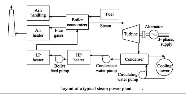
The steam power plant is also called as the thermal power plant. It is the important source to produce the electricity. In thermal power plants, steam is generated by heating the water and is used to rotate the turbines which are coupled with the synchronous generators (also known as alternators) to produce electricity. Steam can be generated from coal, gas or nuclear as the main fuel. Coal, which is the main fuel used in thermal power plants, is fired in the boiler to generate heat for producing steam. The thermal efficiency of a steam power plant mainly depends on the choice of the steam cycle and varies from 28% to 35%. The principal equipment of steam power plants is the boiler, super-heater, feed water pump, steam reheater, condenser, turbine, and generator. The major components of the steam generating plants are shown in Figure. In large thermal power plant unit, several stages of turbines such as high pressure, intermediate pressure and low pressure are used to extract more power from the steam and thus, to increase the efficiency of the machine with minimum cost. For generating the electricity using the steam turbine, high-speed synchronous generators al used because the efficiency of steam turbines is high at high speed. Since the speed of turbo alternator is high, the diameters of the machine are kept minimum so that the centrifugal fort acting on the rotor is minimized. To keep the same electrical loading (which is proportional area x length), the length of the turbo-alternators is increased.