
Ques.91. When both the junctions of bipolar junction transistor (BJT) are in forward biased, then in which region BJT will operate?
- Ohmic region
- Cut-off region
- Saturation region✓
- Active region
The output characteristics can be divided into three distinct regions. namely, the active region, the saturation region, and the cut-off region. In the active region, the collector junction is reverse biased and the emitter junction is forward biased. In the output characteristics, the active region is the area to the right of the ordinate VCE= a few tenths of a volt and above IB = 0. In this region, the transistor output current responds most sensitively to an input signal. If the transistor is to be used as an amplifying device without appreciable distortion, it must be restricted to operate in this region. In the active region, IC is practically independent of VCE and is determined only by lE. The active region lies between cutoff and saturation points. The region of the output characteristics where both junctions (emitter and collector) are forward biased, is known as the saturation region of the transistor. The saturation region is located to the left of the ordinate. VCB is slightly positive for a p-n-p transistor in this region. This forward biasing of the collector-base junction causes the collector current to change exponentially with the collector-base forward voltage, as in p-n diode. The large change in the collector current for a small change in VCB in the saturation region is thus accounted. A forward bias implies that the collector p material is at a positive potential relative to the base n material. A hole current thus flows from the collector to the base, i.e., in a direction opposite to the original hole current due to the transistor action. When the forward-bias is sufficiently large, the hole flow from the collector to the base predominates, forcing Ic to be positive, as shown in Fig. The region of the output characteristics where both the junctions (emitter and collector) are reverse biased, is known as the cutoff region of the transistor. In order to cut-off the transistor, it is not enough to reduce lB to zero. Instead, it is necessary to reverse bias the emitter junction slightly. The cut-off is thus defined as the condition where the collector current is equal to the reverse saturation current ICO and the emitter current is zero. Note:- Cutoff region: in this region transistor acts as off switch. Saturation region: transistor acts as on switch. Active region: transistor acts as an amplifierActive Region
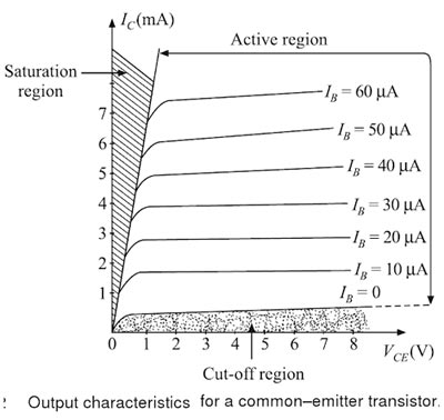
Saturation Region
Cut-off Region
Ques.92. Essential features of switchgear are:-
- Absolutely certain discrimination
- Complete reliability
- Quick Operation
- All of these✓
SWITCHGEAR DEFINITION:- Switchgear is a general term covering switching and interrupting devices that control, meter and protect the flow of electric power. Requirement of Protection System A basic requirement of a protective system is to clear the fault with a sufficient speed to minimize the adverse effects of the fault. To fulfill this requirement, a protective system is required to possess the following properties. Reliability & Simplicity:- Reliability means that the protection system must be ready to function correctly at all times and under all condition of fault and abnormal conditions of the power system for which it has been designed. The relaying scheme can be kept in proper condition through careful maintenance and accurate record-keeping of all the elements including the relay circuit-breaker, PT, CT, transducers, battery, and wiring, among other things. Simplicity and robustness of the relaying equipment also ensure their reliability under the adverse system and environmental conditions. A typical value of the reliability of a protective scheme must not be less than 95 percent. Selectivity– Selectivity is the ability of a protective system to isolate only a fault section of a system from rest of the healthy power system. Selectivity is absolute if the protective scheme responds only to faults within its own zone. Whereas it is said to be relative if it is obtained by grading the settings of the protective relay of different zones, all of them respond to a given fault. The absolutely selective protective systems are known as unit systems; whereas the protection systems, it which selectivity is relative are known as non-unit systems. As for example, differential protection is said to be a unit protective system; whereas current time graded overcurrent protection or distance protection are said to be non-unit protective systems. Speed:- Speed refers to the total fault clearing time of a protective system including the protective relay tripping time as well as time taken by the breaker to open and to extinguish the arc produced between its contacts. It is obvious that faster the speed of operation of the elements of a protective system (relay and breakers), lesser is the damage to the power system components. This also limits the ionization at the fault, increases the chances of a successful auto-reclosing and reduces the dead time interval of a power system. Moreover, the quick disconnection of the faulty section for the rest of the healthy system helps in maintaining the stability of the power system. Discrimination:- A protection system should be able to discriminate between the faulty condition and the normal loading conditions, particularly, when the minimum fault current is less than the maximum load current. As for example, while protecting a power transformer, the protective system must be able to distinguish between a fault and a magnetizing inrush. Stability:- The term stability is often used to describe the quality of a protective system by virtue of which it remains inoperative under all conditions associated with faults outside their own tripping zone. In other words, it can be said that the protective system should remain stable against any type of disturbance present at any point of the power system except for an in-zone electrical fault.
Ques.93. There is three terminal in an operational amplifier, they are 2 inputs and 1 output. What does the third one represent?
- Source and drain
- Sink and Source✓
- Drain and Gate
- Inverting and Non-Inverting
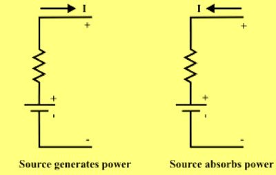
The operational amplifier (popularly known as an op-amp) is an active device used to design circuits that perform useful operations, such as generating sine waves or square waves; amplifying, combining, integrating, differentiating and removing noise; and transforming alternating current into direct current and vice-versa. It can also change the shape of a waveform, produce a change in the output when an input signal reaches a certain level, provide constant voltage or current, and perform various other important circuit operations. Op-amp circuits are very important as we develop a valuable perception about how electronic circuits work in general. An op-amp is a very high-gain differential amplifier with high input impedance and low output impedance. The figure shows a basic op-amp with two inputs and one output. The negative terminal is known as the inverting input terminal (Input 1), and the positive terminal is known as the non-inverting input terminal (Input 2). Bach input results in an output, which further depends upon the input that is being applied to positive (+) or negative ( – ) input terminals. The op-amp is known as the differential amplifier because it amplifies the voltage difference of the inverting and non-inverting terminals. A third terminal represents the operational amplifiers output port which can both sink and source either a voltage or a current. Current Sourcing When a load is connected to a device so that the device supplies current to the load (sources current) then the configuration is said to be current sourcing. Current Sinking When a load is connected to a device so that current flows from the power supply through the load and into the device, then the configuration is said to be current sinking. When current flows into the device, it is said to be sinking current. The power absorbed or dissipated by any circuit element when flows in a load element from higher potential point (i.e +ve terminal toward the lower terminal point (i.e., -ve terminal). This situation is observed who charging a battery or source because the source is absorbing power. On the other hand, when current flows in a source from the lower potential point (i.e., -ve terminal) town the higher potential point (i.e., +ve terminal), we call that source is generating power or delivering power to the other elements in the electric circuit. In this case, one can no that the battery is acting as a “source” whereas the other element is acting as a “sink” Fig:- shows the mode of current entering in an electric element and it behaves either source (delivering power) or as a sink (absorbing or dissipating power). PROPERTIES OF THE IDEAL OPERATIONAL AMPLIFIER An ideal op-amp should have the following properties: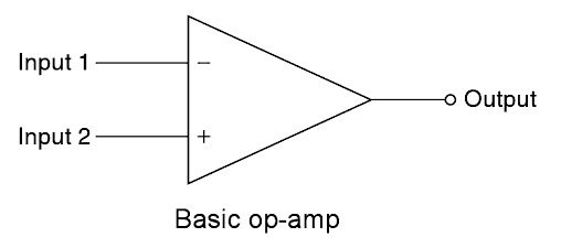
Ques.94. What kind of device is a field effect transistor?
- Non-Semiconductor
- Unipolar semiconductor✓
- Bipolar semiconductor
- Insulator
Transistors may be bipolar or unipolar. In bipolar transistors (which can be either PNP or NPN type), both holes and electrons take part as charge carriers in the operation of the transistor e.g. Hence the name bipolar transistor. The field-effect transistor (FET) is a popular active device of electronics which is widely used for amplification as well as switching similar to the bipolar junction transistor (BJT). The operation of this device depends on the control of the flow of current by the virtue of electric field. Here the flow of charge carriers between drain and source is under the control of the externally applied electric field. The externally applied electric field penetrates into the conducting channel and controls its flow. This electric field is established by application of an external voltage across another two terminals (perpendicular to the flow of carrier) namely gate and source. Since the current flow in the FET is through either P-type or N-type channel hence it is called a unipolar device. Therefore the operation of the device is based on the flow of only one type of charge. Only majority carriers contribute to the flow of current and minority carriers have no role to play in the process of operation, unlike BJT. The greatest advantage with FET is that it has very high input impedance, which is the prime requirement for a voltage amplifier. The input impedance of the device can even tend to a very large value of the order of hundreds of megaohms.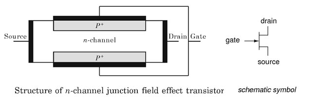
Ques.95. The value of anode current required to maintain the conduction of an SCR even though the gate signal is removed is called as the:-
- Latching current✓
- Holding current
- Switching current
- All of these
Latching Current (IL) The latching current is the minimum value of anode current to trigger or turn ON the thyristor from its OFF state to ON state even after the trigger pulse is removed. To trigger an SCR, the anode current must be build up to the latching current before the gate pulse is removed. Holding Current (IH) The holding current is the minimum value of the anode current to hold the thyristor in ON state. During turn OFF, the anode current should be below the holding current. Usually, the value of holding current is in milli-ampere. Gate Current (Ig) The gate current is required at the gate of the thyristor to turn ON. There are two types of gate current: minimum gate current Igmin and maximum gate current Igmax. Igmin is the minimum value of gate current which is required at the gate to trigger the thyristor from its OFF state to ON state and its value depends on the rate of rise of current. Igmax is the maximum value of gate current that can be applied to the device for turn-on without damaging the gate. The turn-ON time of thyristor reduces with the increase of gate current.
Ques.96. _________ Anode current waveforms will have the minimum junction temperature.
- AC
- 100% DC
- 25% DC✓
- 50% DC
Duty cycle is another unit for measurement for PWM signals. While a pulse width is measured in time, duty cycle is measured as a percentage—on-time versus off-time. Duty cycle refers to the percentage of time that a PWM signal is high or on, in comparison to off-time. One on- and off-time for a PWM signal represents one cycle. Duty cycle units are expressed as a percentage of cycle time. For example, if the pulse width is 0.8 seconds and the off time is 0.2 seconds, a cycle is 1 second in length. This means the duty cycle is 80%. A 100% duty cycle means the signal is on all the time, while a 0% duty cycle is off. Another way of expressing this relationship is signal off-time versus on-time. A signal that is applied for three-quarters of a cycle is 75% duty cycle. N % DC is nothing but a wave with n % duty cycle. Lower the Duty cycle lesser is the current flowing & lesser is the temperature dissipation.
Ques.97. _________ is used for non conventional system to generate electrical energy form.
- Diesel electrical system
- Nuclear system
- Tidal energy✓
- Thermal energy
Classification of Energy Resources: 1. Based on the usability of energy (a) Primary resources:- Resources available in nature in raw form are called primary energy resources, e.g. fossil fuels (coal, oil, and gas), uranium, hydroenergy, etc. These are also known as raw energy resources. Generally, this form of energy cannot be used as such. These are located, explored, extracted, processed and are converted to a form as required by the consumer. (b) Intermediate resources:- This is obtained from primary energy by one or more steps of transformation and is used as a vehicle of energy. (c) Secondary resources:- The form of energy, which is finally supplied to the consumer for utilization, is known as secondary or usable energy, e.g. electrical energy, thermal energy (in the form of steam or hot water), chemical energy (in the form of Hydrogen or fossil fuels), etc. 2. Based on traditional use (a) Conventional Energy resources, which have been traditionally used for many decades, are called conventional energy resources, e.g. fossil fuels, nuclear and hydro resources. (b) Non-conventional Energy resources, which are considered for largescale use after the oil crisis of 1973, are called non-conventional energy sources, e.g., solar, wind, biomass, Tidal etc. 3. Based on long-term availability (a) Non-renewable Resources, which are finite and do not get replenished after their consumption, are called non-renewable, e.g. fossil fuels, uranium (b) Renewable Resources, which are renewed by nature again and again and their supply is not affected by the rate of their consumption are called renewable e.g. solar, wind, biomass, ocean (thermal, tidal and wave), geothermal, hydra, etc. 4. Based on the commercial application (a) Commercial energy resource:- The secondary usable energy forms such as electricity, petrol, diesel, gas, etc. are essential for commercial activities and are categorized as the commercial energy resource. The economy of a country depends on its ability to convert natural raw energy into commercial energy. (b) Non-commercial energy:- The energy derived from nature and used directly without passing through the commercial outlet is called non-commercial resource, e.g. wood, animal dung cake, crop residue, etc.
Ques.98. How can we measure the battery capacity in SI units?
- Wh
- Ah✓
- kWh
- Vh
The amount of energy that a battery can store is caged its capacitor. A water tank, for example, with a capacity of 8000 liters can hold at most 8000 liters. Similarly, a battery can only store a fixed amount of electrical energy, typically marked on the side of the battery by the manufacturer. Actually battery capacity is measured in the amount of charge it can hold. Now we know the current is charge per unit time, therefore the product of current and time gives us the charge. That is why battery capacities are measured in milliampere-hour in case of cellphone batteries or ampere-hour in case of automotive batteries. Battery capacity = charge stored = current x time or amp-hr. The capacity of a battery is measured h amp hours (Ah). This indicates the amount of energy that can be drawn from the battery before it is completely discharged A battery of 100 Ah should ideally give a current of 2 amps for 50 hours (i.e. 2 amps times 50 hours equals 100 amperes).
Ques.99. Find the odd one out regarding the Ohm’s Law.
- Vacuum tubes✓
- Conductor
- DC circuit
- High voltage circuit
OHM’S LAW According to Ohm’s law, the current passing through a conductor is directly proportional to the potential difference between its ends, provided the physical conditions such as the temperature of the conductor remain unchanged. i.e. V = RI The conductors, which obey the Ohm’s law are called the ohmic conductors or linear resistances. All metallic conductors (such as silver, aluminum, copper, iron, etc.) are the ohmic conductors or linear resistances. The conductors, which do not obey the Ohm’s law are called the non-ohmic conductors or non-linear resistance. Examples are the diode valve, triode valve, transistors, electrolyte, etc. Limitations of Ohm’s Law
Ques.100. Consider an n-channel MOSFET having width W, length L and electron mobility in the channel is µn and capacitance per unit area is C_ox. If gate to source voltage V_GS = 0.7V, drain to sour voltage V_DS = 0.2 V, µ_nC._ox = 120µA/V, threshold voltage V_T = 0.4V and (W/L) = 60. Calculate the transconductance gm in mA/V
- 2.5mA
- 1.65mA
- 3mA
- 1.44mA✓
Given VGS =0.7 Linear (Ohmic) Region – with VGS > Vthreshold and VDS < VGS the transistor is in its constant resistance region behaving as a voltage-controlled resistance whose resistive value is determined by the gate voltage, VGS level. The magnitude of current increases linearly with increasing drain voltage till a particular drain voltage determined by the following relations – VGS ≥ Vth VDS < VGS – Vth For Linear region ${I_D} = \dfrac{{{\mu _n}{C_{ox}}{W_N}}}{{{L_N}}}\left[ {\left( {{V_{GS}} – {V_{TN}}} \right){V_{DS}} – \dfrac{{V_{DS}^2}}{2}} \right]$ where, μN is the mobility of electrons in the drain-source channel in cm2/Vsec Cox is the gate oxide capacitance in F/cm2 WN is the width of the NMOS transistor LN is the length of the NMOS transistor VTN is the threshold voltage of the NMOS transistor Now for transconductance gm diffrentiate the above equation by VGS gm = δID/δVGS = μN.Cox.VDS.[W/L] =120 × 10–6 × 60 × 0.2 = 1.44 mA
VDS = 0.2
VTh = 0.4V
VDS < VGS – VTh = 0.7 – 0.4 = 0.3

