
Ques.61. Overload relay are of _____ type.
- Thermal
- Electromagnetic
- Solid State
- All of these✓
Overload protection One of the most important relays for the detection of abnormal conditions is the overload relay which is applied to the protection of motors. The overload relay differs from the overcurrent relay in the following ways. Whereas the overcurrent relay must operate quickly in times of around or less than 1 s the overload relay is associated with times of tens of seconds to several minutes. Overloads should not be confused with fuses or circuit breakers. Fuses and circuit breakers are designed to protect the circuit from a direct ground or short-circuit condition. Overloads are designed to protect the motor from an overload condition. Assume, for example, that a motor has a full-load current rating of 10 amperes. Also, assume that the motor is connected to a circuit that is protected by a 20-ampere circuit breaker. Now assume that the motor becomes overloaded and has a current draw of 15 amperes. The motor is drawing 150% of full-load current. This much of an overload will overheat the motor and damages the windings. But, because the current is only 15 amperes, the 20-ampere circuit breaker does not open the circuit to protect the motor. Overload relays are designed to open the circuit when the current becomes 115% to 125% of the motor full-load current. The setting of the overload is dependent on the properties o the motor that is to be protected. Overload Properties There are certain properties that all overload relays must possess in order to protect a motor: Type of Overload relay Magnetic overload relay reacts only to current excesses is are not affected by temperature. As the name implies, thermals overload relays depend on the rising temperature caused by the overload current to trip the overload mechanism Thermal overload relays can be further subdivided into two types, melting alloy and bimetallic. In the melting alloy type, the heat produced by an overload current causes the solder to melt, permitting a spring-loaded ratchet wheel to turn and open a set of contacts. In the bimetallic strip type, the heat produced by overload current causes a deflection of the bimetal and opens a set of contacts. The beating elements of each type must be matched to the load. Each type is equipped with optional manual or automatic reset mechanisms. A solid-state relay (SSR) is an electronic switching device that switches on or off when a small external voltage is applied across its control terminals. When solid-state relays were introduced, they offered many advantages over electromechanical relays. The fundamental difference between electromechanical relays and solid-state relays is that electromechanical relays respond to input energy whereas solid-state relays process input voltage and current waveforms (signals). Solid-state relays are more accurate than electromechanical relays.
Ques.62. A thermal protection switch can protect against:-
- Overload✓
- Short-circuit
- Temperature
- None of these
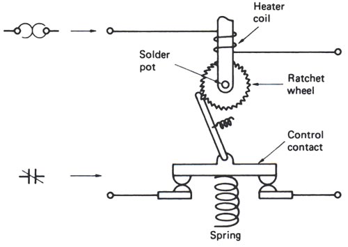
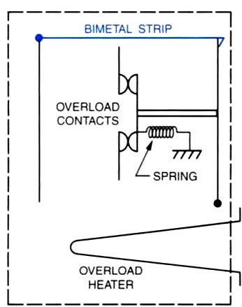
Thermal protection switch protects against the overload. Thermal overload relay or switches can be divided into two types:- Melting overload Relay or Solder Melting Pot To create this type of overload, a bra shaft is placed inside a brass tube. In these overload relays (also referred to as “solder pot relays”), the motor current passes through a small heater winding. The heating element is connected in series with the motor. The current that flows through the motor windings also flows through the heating element. The heating element is calibrated to produce a certain amount of heat when a predetermined amount of current flows through it. As long as the current flowing through it does not exceed a certain amount, there is not enough heat produced to melt the solder. Under overload conditions, an excessive amount of current will flow through the heater causing excessive heat the heat causes a special solder to melt, allowing a ratchet wheel to spin free, opening the contacts. When this occurs, the relay is said to ” trip.” To obtain appropriate tripping current for motors of different sizes, of different full-load currents, a range of thermal units (heaters) is available. The heater coil and solder pot are combined in a one-piece, non-tamperable unit. The heat transfer characteristic and the accuracy of the unit cannot be accidentally changed, as is possible when the heater is a separate component. Melting alloy thermal overload relays are “hand reset,” thus after they trip they must be reset by a deliberate hand operation. A reset button is usually mounted on the cover of enclosed starters. Thermal units are rated in amperes and are selected on the basis of motor full-load current. Bimetal type Overload Relay The bimetal type of overload operates very similarly to the solder-melting type except a bimetal strip is used to cause the contacts to open. In this unit, the bimetal strip is used to mechanically hold the spring-loaded contacts closed. If the current flow through the heater becomes excessive the bimetal strip will warp and permit the spring to open the contacts. After the overload unit has tripped the bimetal strip must be allowed some time to cool before it can be reset. This type of unit has an advantage over the solder-melting type in that it, be adjusted for manual reset or automatic. The solder-melting type of overload must be manually reset.
Ques.63. What is the relation between the length of the cable and the capacitance?
- Equal
- Directly Proportional✓
- Indirectly proportional
- No Relation
The capacity of the capacitor plates can be calculated by the formula : C = (£ × D × L) ⁄ d Where D is the width of the capacitor plates L is the length of the capacitor plate d is the distance between the two plates of the capacitor £ is the dielectric constant. According to the cable length measurement principle of capacity conversion capacitor, an open end cable is regarded as a capacitor. Two cores of the cable regarded as two plates of the capacitor. The effective width of the cable core can approximately be interpreted as D in the formula. The length of the cable can be regarded as the length in the formula. The distance of the cable cores can be interpreted as d in the formula. For the two core wire cable whose internal structure, £, D and d fixed, the capacitances between the two wires of the cable are directly proportional to the cable length. That is C1/C2 = L1/L2 The cable length can be obtained by measuring the cable capacitance per unit length. or
Ques.64. What is the capacity of India’s biggest thermal power plant?
- 5560 MW
- 5340 MW
- 4760 MW✓
- 4620 MW
More than 65% of India’s electricity generation capacity comes from thermal power plants, with about 85% of the country’s thermal power generation being coal-based. Vindhyachal Thermal Power Station, Madhya Pradesh Vindhyachal Thermal Power Station in the Singrauli district of Madhya Pradesh, with an installed capacity of 4,760MW, is currently the biggest thermal power plant in India. It is a coal-based power plant owned and operated by NTPC. Construction of the plant, which comprised 12 generating units (six 210MW units and six 500MW units), had begun in 1982. The first unit was commissioned in 1987, while the sixth 500MW was commissioned in April 2013. An additional 500MW unit was commissioned in August 2015, increasing the plant’s gross capacity from 4,260MW to 4,760MW. The plant uses coal from the NCL-operated Nigahi mine and water from the discharge canal of Singrauli Super Thermal Power Station. The turbine manufacturers for the Vindhyachal Thermal Power Station include Russian companies LMZ, Electrosila, and the Indian BHEL. The 500MW units were supplied by BHEL.
Ques.65. What is the most suitable method to turn on the SCR device among the following?
- Gate Triggering Method✓
- Forward Voltage Triggering Method
- Temperature Triggering Method
- dv/dt triggering Method
To initiate conduction in SCR the anode voltage must be positive with respect to the cathode. Under this condition, an SCR may be caused to conduct by any of several techniques. Various members of the thyristor family of devices are associated with particular triggering methods described below. Gate Triggering This is the most commonly used method for triggering SCRs. In laboratories, almost all the SCR devices are triggered by this process. By applying a positive signal at the gate terminal of the device, it can be triggered much before the specified breakover voltage. The conduction period of the SCR can be controlled by varying the gate signal within the specified values of the maximum and minimum gate currents. For gate triggering, a signal is applied between the gate and the cathode of the device. Three types of signals can be used for this purpose. DC Gate Triggering In this method, a dc voltage of proper magnitude and polarity is applied between the gate and the cathode in such a way that the gate is positive with respect to the cathode. When the applied voltage is sufficient to produce the necessary gate current, the SCR switches on and start conducting. One drawback of this is that the power circuit (anode-cathode circuit) is also dc there is no isolation between the power circuit and the triggering circuit. This method requires a continuous DC signal which causes more gate power loss. AC gate triggering AC source is most commonly used for the gate signal in all application of thyristor control adopted for a.c. applications. This scheme provides the proper isolation between the power and the control circuits. The firing angle control is obtained very conveniently by changing the phase angle of the control signal. However, the gate drive is maintained for the one-half cycle after the device is turned ON, and a reverse voltage is applied between the gate and the cathode during the negative half cycle. Here the SCR is turned on with the positive cycle of an ac gate voltage source. During the positive half-cycle, when the gate current IG reaches IGT. where IGT is the minimum gate current to trigger, the SCR turns on. This method of triggering is used in SCR circuits for ac applications. The drawback of this scheme is that a separate transformer is required to step down the a.c. supply, which adds to the cost. Pulse Gate triggering This is the most popular method for triggering an SCR. In this method, the gate signal consists of a single short duration pulse appearing Periodically or a sequence of high-frequency pulses. The main advantage of this method is that there is no need to apply continuous signals and therefore the gate power losses are very much reduced. Note:- The other TURN-ON method of SCR is Forward voltage triggering:- In this method, the forward voltage is applied between anode and cathode by keeping the gate open. In this case, the junction j2 of SCR is reverse biased. If the applied voltage is increased up to the breakover voltage (VBO) the device becomes turned on. Thermal triggering (temperature triggering):- The width of the depletion layer of an SCR decreases with increasing the junction temperature. Steps in thermal triggering are as follows: (i) Voltage is applied anode to cathode near the breakdown voltage. (ii) Increase the junction temperature to a certain value so theist the reverse-biased junction gets collapsed and the device becomes turned ON. Radiation triggering:- If the light is allowed to bombard on the junction, there is the generation of electron-hole pairs and by increasing charge carriers (electron-hole pairs), the device becomes turned on, eg. LASCR. SCR Turn on Method
Ques.66. What is the decimal equivalent of the hexadecimal Number AF2?
- 2802✓
- 10152
- 2048
- 162
Step1:- Count the digits in AF2, which in this case is 3 digits, and convert each digit to Hex Step 2) Starting from the last number in Step 1, multiply the first number with 1, the second number with 16, and the third number with 256. (See Table 2 for details.) Step 3) Add up all the numbers you got in Step 2 to get the answer. Following the instructions above, your math should look like this: 2 x 1 = 2 2 + 240 + 2560 = 2802
A
B
C
D
E
F
=
=
=
=
=
10
11
12
13
14
15
15 x 16 = 240
10 x 256 = 2560
Ques.67. What is the critical temperature (in Kelvin) for lead below which it shows superconductivity?
- 0.8
- 1.2
- 4.2
- 7.2✓
Superconducting materials are the materials which conduct electricity without resistance below a certain temperature. Superconductivity is one of the most exciting phenomena in Physics, because of the peculiar nature and the wide application of this phenomenon. This phenomenon of superconductivity was first discovered by a Dutch physicist, H.K. Onnes. Superconducting materials are having very good electrical and magnetic properties. Before the discovery of superconductors, it is believed that the electrical resistivity of the material becomes zero, only at the absolute temperature.
The critical temperatures Tc and critical magnetic field strengths Bc(0) for various superconducting elements.
| Tc/K | Bc(0)/mT | |
|---|---|---|
| aluminum | 1.2 | 10 |
| cadmium | 0.52 | 2.8 |
| indium | 3.4 | 28 |
| lead | 7.2 | 80 |
| mercury | 4.2 | 41 |
| tantalum | 4.5 | 83 |
| thallium | 2.4 | 18 |
| tin | 3.7 | 31 |
| titanium | 0.40 | 5.6 |
| zinc | 0.85 | 5.4 |
Ques.68. What is the efficiency of a diesel power station?
- 53-56%
- 22-27%
- 85-90%
- 35-42%✓
Diesel engine power plants are more efficient than the other types of engine plant for the same capacity. The diesel engine plants are more suitable for low- and medium-power outputs. These plants are commonly employed where fuel prices are low and water availability is limited. The capacity of the diesel power plants is about 5 MW, such plants are used as standby plants to hydro- and diesel power plants for small output. These plants do not require a large amount of water for cooling. Diesel engines are widely used in railroad locomotives, road buildings, ship propulsion electric generators for feeding supply to pubs tic industrial and institutional purpose, etc. A wide application of diesel engine is mainly due to the less cost fuel than gasoline products. The efficiency of diesel power station is around 35% to 40%. A diesel power station has high running charges as the fuel (i.e. diesel) used is quite costly. Therefore, such power stations are not used to produce bulk power. A diesel power station is used as a peak load station.
Ques.69. What is the phase difference (in Degree) of input and output voltages of a transistor in a common emitter arrangement?
- 45
- 60
- 90
- 180✓
In the common-emitter configuration, the emitter of a transistor is connected to a common terminal between input and output as shown in Fig. The input signal is applied between the emitter and base terminals. The output will be obtained from the collector and emitter terminals. The common emitter configuration of the transistor is the most commonly used one in circuits. The common emitter transistor amplifier is the only configuration that gives a phase inversion of 180°, between the input and output signals. In a common emitter amplifier input current (let us assume sinusoidal signal) is given to the base and we know that collector current is beta times of base current and as the base current increases collector current increases largely. So during the positive half cycle of the Sinusoidal signal when the base current/ voltage increases collector current increases and the increase in the collector current causes the high voltage drop at collector resistance from where the output is taken. Similarly, the decrease in base current/ voltage and in collector current will increase the collector to emitter voltage. When base voltage & collector/base current are zero collectors to emitter voltage is maximum. When base voltage & collector/base current are at their maximum collector to emitter voltage is at its minimum. It means the output voltage is out of phase. That is Why CE amplifier gives 180 phase shift 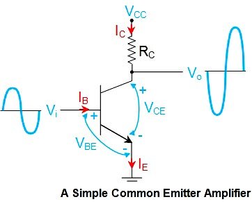
Ques.70. What is used as a prime mover in the gas turbine plant?
- Gas turbine✓
- Diesel
- Water
- Pelton Turbine
Gas turbines are used in electrical power generation, propulsion, and compressor and pump drives. The favourable power output to weight ratio of gas turbines makes them well suited for transport applications such as aircraft propulsion, marine power plants, etc. Gas turbine (GT) power plants tend to be lighter and more compact than the steam turbine based power plants. The thermal efficiency of the gas turbine plant (20-25%) is less when compared to the steam power plant (25-30%). This lower thermal efficiency reduces the load factor and increases the fuel cost but which can be compensated in the gas plant by lowering the fixed, operating, as well as maintenance charges. In India, gas turbine plant of size 70 MW was situated at Namrup in Assam, working as a base-load plant with natural. Depending on the type of prime mover, the most common power plants can be classified in: Steam turbine thermal power plants make use of a steam turbine to drive the electrical generator that is coupled in the same shaft. In a combustion thermal power plant, the prime mover is an internal combustion engine: a gas turbine or a reciprocating motor. The fuel, gas or diesel fuel is burned inside the machine and the combustion gasses themselves exert a force on the blades or the pistons that, in turn, drive the electrical generator. A Gas-turbine power station uses a gas turbine as the prime mover for generating electrical energy. This power station is generally used in conjunction with Steam Power station. In the case of a Diesel power plant, the prime mover is a motor similar to those used in the automotive industry. In hydraulic power plants, the prime mover is a hydraulic turbine that transforms the energy of moving water into rotational mechanical energy. In a wind generator, the prime mover is a wind turbine, which transforms the kinetic energy of moving air into mechanical energy to drive an electrical generator. In photovoltaic plants, there is no prime mover. The electromagnetic energy from solar radiation is directly converted into electricity in a solar panel, with similar characteristics to wind energy.

