
UPPCL JE Electrical question paper with Explanation 2018
Ques.1. The size of the synchronous motor decrease with the increase in:-
- Speed
- Flux density✓
- Horsepower rating
- All of these
Output Equations and Main Dimensions of DC Machine Output equation relates the output and main dimensions of the machine.In general, there is a fundamental electrical machine design rule which says the rating is proportional to diameter squared* length i.e. P = D2L. In general, the output power by a three-phase AC machine is given as P = CoD2L.Ns Where Ns = synchronous Speed in RPS Co is the output coefficient of the DC machine and it is given as Co = π2 × Bav × ac × Kws Where Bav is flux density in the air gap ac = Specific electric loading Kws = winding factor Hence Size of the AC machine is directly proportional to the horsepower and inversely proportional to the flux density and speed. Since the synchronous motor is a constant speed motor, therefore, the size of the motor decreased with an increase in flux density. Since ferromagnetic materials are used as stator/rotor cores, their saturation level determines the maximum allowable flux density. A high value of flux density is achieved by reducing the air gap, but it results in saturation of the core, thereby depleting the power factor and also causes an increased excitation resulting in higher cost for the field system. Hence a higher flux density requires a greater cross-section in the armature teeth to avoid saturation
Ques.2. If the area, current, and the number of turns of an AC circuit is doubled, then the new inductance will be:-
- Twice the former✓
- Four Times the former
- Small
- Half the former
The inductance of the coil is given as L = Nφ ⁄ I = N.B.A ⁄ I where N is the number of turns of the solenoid A is the area of each turn of the coil l is the current in the solenoid Φ is the magnetic flux B is the Magnetic flux density Now the area, current, and the number of turns are doubled then L1 = 2 × 2/2 L1 = 2
Ques.3. If the cathode of the thyristor is made +Ve with respect to the anode & no gate current is applied then:-
- Only the middle junction is forward biased✓
- Only the middle junction is reversed biased
- All the junction are forward biased
- All the junction are reversed biased
SCR is a unidirectional device and like a diode, it allows current to flow in one direction only. It can be used as a switch. The switching of SCR is controlled by the additional input called gate and biasing conditions. It can be used as a rectifier to convert AC signals to DC signals. Construction The SCR is a four-layer p-n-p-n device, where p and n layers are alternately arranged. The outer layers are heavily doped. There are three p-n junctions called J1, J2, and J3. The outer P-layer is called anode and outer n-layer is called cathode, middle P-layer is called the gate. The terminals are taken out from their layers. Anode must be positive with respect to the cathode so that SCR will be forward biased. To turn on an SCR, a current is to be passed through the gate terrninal. Hence it is a current operated device. Working of SCR When the gate is open: Assume that anode is kept positive with respect to the cathode and the gate is open. Junctions J1 and J3 are forward biased and junction J2 is reverse biased. In J2 a small leakage current flows which is negligibly small. Now the SCR is said to be in off condition. This is called forward blocking state of SCR. The voltage applied to anode and cathode is called forward voltage. ⇒ With the gate open, if the cathode is made positive with respect to the anode, the junctions J1 and J3 become reverse biased and J2 forward biased. Still the current flowing is leakage current, which can be neglected as it is very small. The SCR is said to be in reverse blocking state and voltage applied is called reverse voltage. The device behaves as if two diodes are connected in series with the reverse voltage applied across them. Therefore, only a small leakage current (in mA) flow. If the reverse voltage is increased, then at a critical voltage called reverse breakdown voltage VBR, an avalanche will occur at J1 and J3 and the reverse current increases rapidly. A large current associated with VBR gives rise to more losses in the SCR. This may lead to thyristor damage as the junction temperature may exceed its permissible temperature rise. The SCR in reverse blocking may be treated as an open switch because of its offer very high impedance.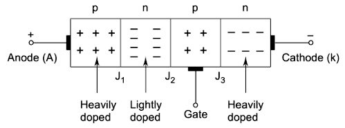
Ques.4. If the total number of slots in a D.C machine is 25 and the total number of poles is 5, then what is the coil span of the machine?
- 5✓
- 30
- 20
- 125
Coil-pitch or Coil-span The distance between the two coil-sides of a coil measured in terms of teeth, slots or electrical degrees. For full pitch, coil span factor is S/P Where S = number of slot or teeth and P is the number of poles Coil span = 25/5 = 5
Ques.5. Which of the following outlines the features of D.C welding over A.C welding?
1.1 The cost of equipment is higher
2. It is less safe as the no-load voltage is high✓
3. The efficiency is lower due to the presence of rotating part
2.1. The cost of equipment is higher
2. it is safer
3. The efficiency is higher due to the absence of rotating part
3.1 The cost of equipment is cheaper
2. It is less safe as the no-load voltage is high
3. The efficiency is higher due to the absence of rotating part
4.1. The cost of equipment is cheaper
2. It is less safe as the no-load voltage is high
3. The efficiency is lower due to rotating the part
Both D.C. and A.C. equipment are employed in arc welding. D.C. arc welding machines are D.C. generators driven by an electric motor or an internal combustion engine. A.C. welding machines are transformers for stepping down the main supply voltage to the voltage (20 to 40V) and current (150 to 1000 A) suitable for arc welding. The Comparision between A.C welding and DC welding are discussed below:- [ninja_tables id=”28565″]
Ques.6. Which of the following will happen if the thickness of the refractory wall of the furnace is increased?
- Energy consumption will be decreased
- The temperature inside the furnace will fall
- The temperature on the outer surface of the furnace wall will drop✓
- Heat loss through furnace wall will be increased
In a furnace we want to have high heat transfer inside the furnace; however, we do not want any heat loss through the furnace wall. Thus to prevent the heat transfer from the furnace to the atmosphere a bad heat conductor or a very good heat insulator is required. In case of the furnace, the wall is prepared by multiple layers of refractory materials to minimize the heat losses. Therefore, wall insulation is required to minimize the heat loss from the system to the environment or heat gain from the environment to the system (like cryogenic systems). Furnace Design The furnace chamber provides space to conduct the activity in the furnace. This chamber design has many issues like shape, size, the ratio of various dimensions, refractory lining thickness, and nature, furnace casing material with proper ports, etc. These factors are briefly discussed below: Chamber shape The furnace chamber shape could be closed rectangular (e.g. reheating furnace), narrow rectangular (e.g. coke oven), closed trough (e.g. open hearth furnace), closed hemispherical shape (e.g. electric arc furnace), open cylindrical shape (e.g. cupola), one end closed cylindrical shape (e.g. induction melting furnace), etc. The shape depends on the process activity and the mode of heat Chamber size The dimensions of rectangular shape furnace (length, width and height), cylindrical shaped (height and diameter) furnace or hemispherical shaped (section diameter and centre height) furnace depend on the scale of operation and process constrains. In case of reheating furnace, the length of the furnace will depend on the object size to be heated and burner design. The width of the furnace will be decided on the number of pieces to be heated (load) at a time, while the height will be decided by the aerodynamics of the furnace for good gas flow and heat transfer. The coke oven chamber dimensions are decided by operating factors. The coke oven length depends on the oven capacity and availability of pusher arm length, the height is decided by selection of heating chamber flue design and the minimum desired width is decided by the ability of a man to enter for construction and repair. In each case, there are compelling parameters to fix the dimensions depending on the furnace capacity. Refractory thickness and nature The nature of refractory is decided by the maximum temperature requirements and other working conditions like the chemical nature of materials in contact, working load, erosion and corrosion parameters, etc. Once the nature of refractory is decided, then the thickness of the refractory layer would depend on the inner working temperature, the thermal conductivity of the refractory and maximum temperature sustainable by the outer metallic casing. Thermal conductivity and heat capacity: in practical applications, refractory materials processing high thermal capacity as well as low thermal conductivity are required, depending upon (of course) the functional requirements. In most situations, a refractory that serves as a furnace wall should have a low thermal conductivity in order to retain as much as heat as possible. However, a refractory used in the construction of the walls of muffles or retorts or coke ovens should have a high thermal conductivity in order to transmit as much heat as possible to the interior. The charge remains separated from the flame in these specific examples of installations. The heat transferred or conducted by a refractory at a rate Q is given by the relationship: Q = K.(T1 − T2) A ⁄ ΔX Where T1 = Temperature on the hotter surface T2 = Temperature on the colder surface A = Area of refractory K = Thermal conductivity ΔX = Thickness From this relationship, it follows that if the refractory wall is made thicker, the heat loss will be decreased. Alternatively, if the refractory brick is backed by an insulating layer, the same result ensues. These provisions tend to cause the refractory material to be at a higher aver age temperature. The increased temperature tends to soften the refractory and to enhance the chemical attack on it. In this scenario, a choice must be made between increased heat savings and a reduction in the life of the refractory material. This particular problem has drawn considerable attention to the design of open-hearth furnaces for steel making. The question of insulating the roofs of these furnaces has been the subject of a great deal of deliberation. The porosity of refractory bricks has a direct bearing on the thermal conductivity. The densest and the least porous bricks have the highest thermal conductivity owing to the absence of air voids. On the other hand, in porous bricks, the entrapped air in the pores acts as a nonconducting material. The heat capacity of a furnace unit at a given temperature depends on bulk density, specific heat and thermal conductivity of the refractory. The heat capacity and thermal conductivity of a refractory increase with increasing bulk density, and decrease with increasing porosity. A refractory with a high bulk density and a high thermal conductivity is desirable from the point of view of certain applications. With refractories used for heat storage and transmission, such as checker bricks, no conflict between properties arises, since high density is a desirable criterion both for stability and for increased heat storage and conductivity. Furnace casing material The furnace is generally encased in steel structure for stability, support, and handling. The steel selected is generally common structural steel unless some furnace demand heat resisting steel for special applications. The steel casing thickness depends on the furnace size and loads subjected. The steel casing is made sufficiently strong to sustain rough working conditions of the furnace. This casing has ports for the burner, gas exit, material charging and discharging door, etc. Burners The burners are necessary to combust the fuel for generating thermal energy for its efficient utilization in the furnace. The suitable burners are selected based on the type of fuel (coal, oil or gas) best suited for the furnace.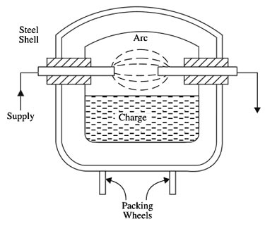
Ques.7. Calculate the energy efficiency when the input energy is 3000J and output energy is 1000J.
- 0.5
- 0.03
- 0.3
- 0.333✓
The efficiency is the ratio of energy output, divided by the energy input, η = Output energy/Input energy Input energy = 3000 joule Output energy = 1000 joule η = 1000/3000 = 0.333
Ques.8. A circuit breaker must be equipped for remote operation with which of the following?
- Inverse Time Trip
- Shunt Trip✓
- Time Delay Trip
- None of these
TRIP ELEMENTS Trip elements trip the operating mechanism of a circuit breaker during either a prolonged overload or a short-circuit current. Some circuit breakers have a screwdriver slot located on the front of the trip unit used for adjusting sensitivity. The maximum setting is established by the protection of the minimum conductor size in the circuit. Shunt Trips A shunt trip or under-voltage trip is a mechanism which trips a circuit breaker by means of a trip coil energized from a separate circuit or source of power. Circuit breakers for industrial use are automatic, three-phase switches that can interrupt load currents under fault conditions. They are equipped with a complex over-toggle mechanism, operating either manually (handle) or remotely (motor and gear train) for closing or opening their contacts. In both cases, a strong spring is compressed and stores energy that can be released during the opening of the circuit breaker. In order to enable this action, a solenoid-produced force with the capacity to open a circuit breaker is needed. Such a solenoid is called a “shunt trip coil”. A shunt trip relay completes the circuit between the control-power source and the solenoid coil. Shunt trips are used to trip a circuit breaker electrically from a remote location and consist of a momentary-rated solenoid tripping device mounted inside a molded case. The shunt trip can remotely trip the breaker but cannot remotely reclose the breaker. To reclose the breaker, the breaker handle must first be moved to the reset position and then to the “on” position. Instantaneous Magnetic Trip Magnetic trips work by using an electromagnet in series with the load current. When the current reaches the set point, the electromagnet instantaneously trips. This type of trip is commonly found in low-voltage breakers (e.g., household circuit breakers). Thermal Trip Considered the industry standard, these trip elements work using a bimetal heated by the load current. When overheated, indicating an overload, the bimetal will deflect, which causes the operating mechanism to trip. Electronic Trip Current transformers and solid-state circuits are used to monitor the current. When an overload or short circuit is detected, the monitors initiate a trip. Electronic trip elements can include trip features and flexibility not present in other types of trip elements (e.g., adjustable pickup, time delays, instantaneous pickup, selective interlocking). Solid-state components have replaced electromechanical-magnetic and thermal-magnetic trip elements in some molded-case breakers. Thermal Magnetic Trip A thermal-magnetic trip, in addition to providing short-circuit protection, guards against long-term current overloads existing longer than roughly 10 seconds. Because bimetal deflection is dependent on current and time, the thermal unit provides a longtime delay for light overloads and fast response for heavy overloads. The thermal magnetic unit may be ambient-temperature sensitive (breaker trips at a lower current as ambient temperature rises). The National Electrical Code (NEC) defines the current at which a long-time-delay thermal element must initiate circuit-clearing operation. The NEC specifies a point that is 125% of the rated equipment or conductor ampacity. The circuit breaker will take no action below this current. For conventional (non-compensating) thermal-magnetic elements, the thermal portion defines the continuous current rating of the breaker (specified as 100% at 40°C). The thermal element current rating cannot exceed the frame rating. Manufacturers recommend that continuous current through the breaker be limited to 80% of the frame size.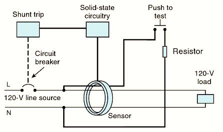
Ques.9. The ________ region has the highest area in the transistor
- Collector✓
- Base
- Base-Emitter
- Emitter
A Bipolar Junction Transistor (BJT) is a three-layer, two junction semiconductor device consisting of either two N-type and one P-type layer of material (NPN transistor) or two P-type and one N-type layer of material (PNP transistor). There are three regions in which the transistors operate Active Region: The transistor is said to operate in active region when the emitter junction is biased in forward direction and the collector junction in the reverse direction. The transistor is used as an amplifier when it is biased in an active region. This active region of operation in a transistor is the most sensitive region of operation in a transistor. The variation of output collector current depends on the input emitter current variations. Even though the magnitude of an output current is small compared to that of the input current, the variation is very sensitive.
Ques.10. The circuit breaker is a device that is used for protection of circuit. The circuit breaker is an example of:
- Arresters
- Conductor
- Switchgear✓
- None of these
SWITCHGEAR DEFINITION:- Switchgear is a general term covering switching and interrupting devices that control, meter and protect the flow of electric power. or The apparatus used for switching controlling and protecting the electrical circuits and equipment is known as switchgear. The component parts include circuit breakers, instrument transformers, transfer switches, voltage regulators, instruments, and protective relays and devices.

